
Direct current-direct current (DC) conversion circuit

A technology of DC-DC and conversion circuits, applied in the field of DC-DC conversion circuits, can solve problems such as inability to reset, transformer volt-second unbalance, magnetic core deviation, etc., and achieve the effect of reducing volume

Active Publication Date: 2015-07-08
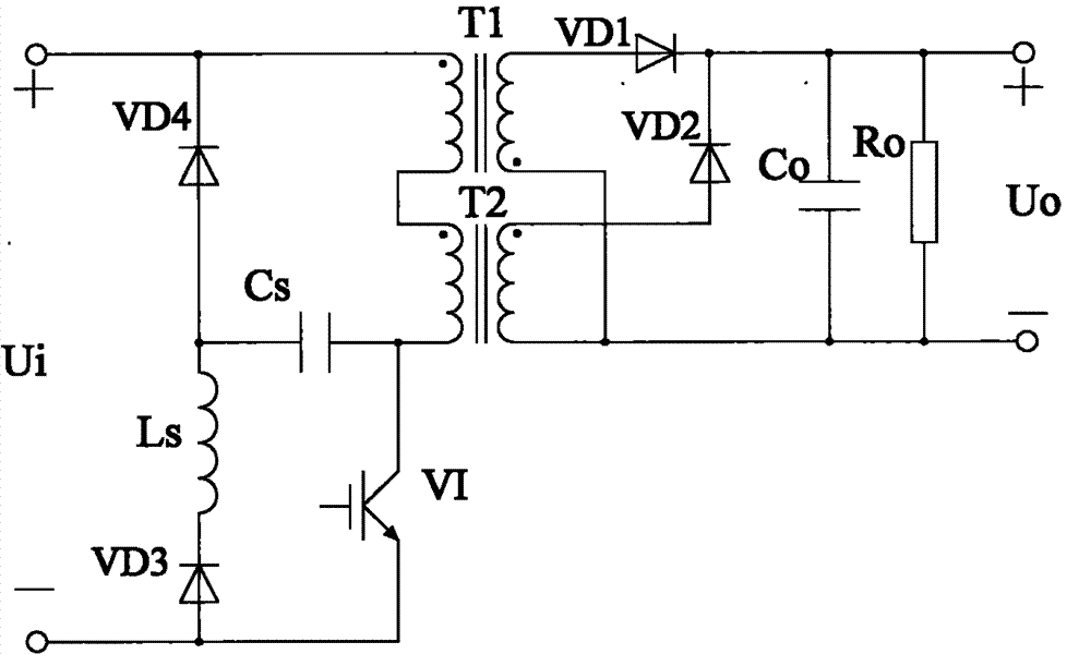
INVENTRONICS HANGZHOU
View PDF15 Cites 0 Cited by
  • Summary
  • Abstract
  • Description
  • Claims
  • Application Information

AI Technical Summary

Problems solved by technology

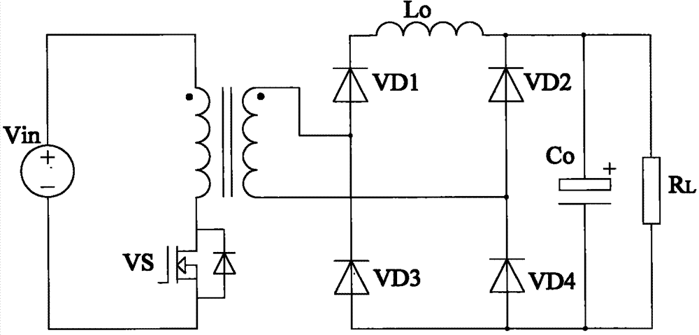
The disadvantage of this circuit is that the current of the inductor Lo can only work in the discontinuous mode. If it works in the continuous mode, the transformer will be unbalanced in volt-seconds, causing the magnetic core to deviate and cannot be reset; the average current in the positive and negative directions of the secondary winding of the transformer cannot be guaranteed. equal value

Method used


Image

  • Direct current-direct current (DC) conversion circuit
  • Direct current-direct current (DC) conversion circuit
  • Direct current-direct current (DC) conversion circuit

Examples


Embodiment Construction

[0051] In order to make the above objects, features and advantages of the present invention more comprehensible, specific implementations of the present invention will be described in detail below in conjunction with the accompanying drawings.

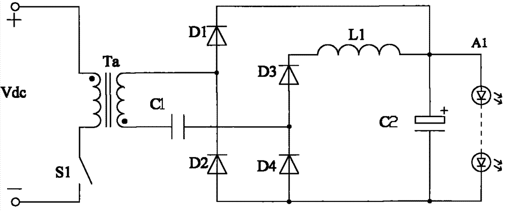
[0052] see image 3 , which is a structural diagram of Embodiment 1 of the DC-DC conversion circuit provided by the present invention.

[0053]The DC-DC conversion circuit provided in this embodiment includes: a switch tube S1, a transformer Ta, a first capacitor C1, a first diode D1, a second diode D2, a third diode D3, and a fourth diode Tube D4, first inductor L1 and filter capacitor C2;

[0054] The same-named end of the primary winding of the transformer Ta is connected to the positive pole of the power supply Vdc, and the different-named end is connected to the negative pole of the power supply Vdc through the switch tube S1;

[0055] The terminal with the same name of the secondary winding of the transformer Ta is sequentially...


PUM


Abstract

A DC-DC converting circuit includes a switch (S1), a transformer (Ta), a first capacitor (C1), a first diode (D1), a second diode (D2), a third diode (D3), a fourth diode (D4), a first inductor (L1) and a filtering capacitor (C2). The dotted terminal of the primary winding of the transformer (Ta) is connected to a positive terminal of a power supply (Vdc). The synonym terminal of the primary winding of the transformer (Ta) is connected to the negative terminal of the power supply (Vdc) through the switch (S1). The dotted terminal of the secondary winding of the transformer (Ta) is connected to the synonym terminal of the secondary winding of the transformer (Ta) through the first capacitor (C1), the third diode (D3), the first inductor (L1), the filtering capacitor (C2) and the second diode (D2) which are sequentially connected in series. The synonym terminal of the secondary winding of the transformer (Ta) is connected to the dotted terminal of the secondary winding of the transformer (Ta) through the first diode (D1), the filtering capacitor (C2), the fourth diode (D4) and the first capacitor (C1) which are sequentially connected in series. The circuit benefits the reduction of the volume of the transformer and the capacitance of the filtering capacitor. By the presence of the first capacitor, the volt-second balance of the transformer and the equalization of the average value of the forward current and the backward current of the secondary winding in the transformer are guaranteed.

Description

technical field [0001] The invention relates to the technical field of power electronics, in particular to a DC-DC conversion circuit. Background technique [0002] The DC-DC conversion circuit is used to supply power to DC loads. The DC-DC conversion circuit in the prior art will be described in detail below with reference to the accompanying drawings. [0003] see figure 1 , which is a structural diagram of a DC-DC conversion circuit in the prior art. [0004] The DC-DC conversion circuit is a paper published in the 2nd issue of "Electronic and Electronic Technology" in 1998. The forward and flyback circuit on the primary side includes a forward transformer T2, a flyback transformer T1, a switch tube VI, a first diode VD1, a second diode VD2, a capacitor Co and a resistor Ro, and also includes a third diode The circuit composed of the tube VD3, the fourth diode VD4, the inductor Ls, and the capacitor Cs forms a reset circuit of the forward transformer T2. [0005] Whe...

Claims


Application Information

Patent Timeline
Patent Type & Authority Patents(China)
IPC IPC(8): H02M3/315
CPCH05B33/0815H02M3/338H05B45/3725H05B45/382
Inventor 姚晓莉葛良安
Owner INVENTRONICS HANGZHOU
Learn More