Reinforcing steel bar structure of hinge joint

A technology of steel bars and hinged joints, which is applied in the field of steel-concrete composite structures, can solve problems such as poor tensile strength, poor shear resistance, and easy damage to hinged joints, so as to improve shear resistance, prevent mutual separation, and improve connection performance effect

Active Publication Date: 2015-07-15
SOUTHEAST UNIV
View PDF5 Cites 2 Cited by
  • Summary
  • Abstract
  • Description
  • Claims
  • Application Information

AI Technical Summary

Problems solved by technology

[0004] Purpose of the invention: In order to overcome the deficiencies in the prior art, the present invention provides a steel bar structure with hinged joints, which solves the problem of poor shear resistance, poor tensile resistance and easy hinged joints in the existing steel bar structure. Damage, issues affecting bridge safety

Method used


Image

  • Reinforcing steel bar structure of hinge joint
  • Reinforcing steel bar structure of hinge joint
  • Reinforcing steel bar structure of hinge joint

Examples


Embodiment

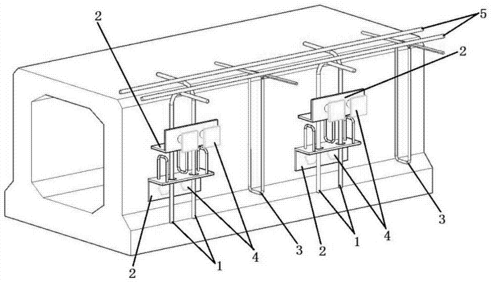
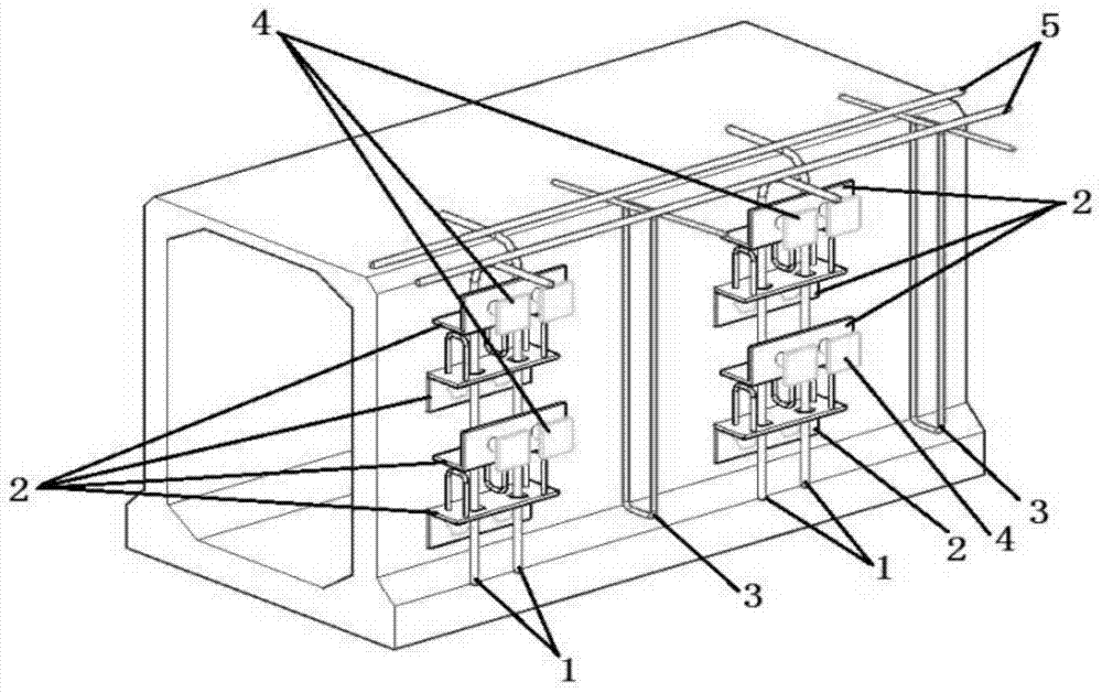
[0021] Example: such as figure 2 As shown, there are two restraint structures, one restraint structure includes two pairs of folded plates 2 and two restraint reinforcement bars 1, and there are four pairs of folded plates 2 in total.

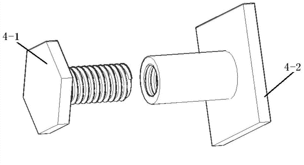
[0022] The folding plate 2 is as Figure 4 As shown, there are L=2 restraining steel bar holes 2-2 on a folding surface of the folding plate 2, and three reinforcing bars 2-1 are arranged between the opposite folding surfaces of every pair of folding plates 2, and the two reinforcing bars 2-1 of each pair of folding plates 2 The ends are welded on the same folding surface and the steel bar 2-1 and the folding surface form a closed geometric shape, and a pair of opposite restraint reinforcement holes 2-2 are separated between adjacent closed geometric shapes, and the adjacent closed geometric shapes The steel bars 2-1 are respectively welded on the opposite folding surfaces, that is, one is welded on one folding surface, and two are welded on ...


PUM


Abstract

The invention discloses a reinforcing steel bar structure of a hinge joint. The reinforcing steel bar structure comprises a plurality of restraining structures, stirrups and straight reinforcing steel bars, wherein the restraining structures, the stirrups and the straight reinforcing steel bars are fixed into a gap of the hinge joint, and the height direction is defined to be the y axis. Each restraining structure comprises M restraining reinforcing steel bars and N pairs of folding plates, each pair of folding plates are fixed to the wall faces of two adjacent concrete beams through fastening pieces respectively, L restraining reinforcing steel bar holes are formed on the folding faces of the folding plates, the central axes of all opposite restraining reinforcing steel bar holes of the folding plates are located in a straight line parallel to the y axis, one end of each restraining reinforcing steel bar penetrates through the corresponding restraining reinforcing steel bar hole with the central axis located in the straight line parallel to the y axis, the other end of each restraining reinforcing steel bar is bent and is attached to the top face of the corresponding concrete beam, the hoops are arranged between every two adjacent restraining structures, and all the hoops and all the bent ends of the restraining reinforcing steel bars are bound with the straight reinforcing steel bars to form a reinforcing steel bar net. The reinforcing steel bar structure of the hinge joint solves the problem that safety of a bridge is affected due to the fact that a reinforcing steel bar structure of an existing hinge joint is poor in shearing resistance performance and poor in tensile property and the hinge joint can be easily damaged.

Description

technical field [0001] The invention relates to a hinged steel bar structure, which belongs to the field of steel-concrete composite structures. Background technique [0002] Simply supported concrete girder bridges have the advantages of simple construction and low cost, so bridges with spans below 20m mostly adopt this type of structure. The transverse load distribution is realized by transferring shear force between the concrete beams through hinge joints, and the transverse connection between hinge joints and bridge deck pavement enables multiple concrete beams to bear external loads as a whole. However, after several years of service in concrete girder bridges, typical defects such as longitudinal cracking of the bottom surface of the beam slab, longitudinal cracking of the deck pavement along the hinge joint, and partial loss of concrete at the hinge joint will appear in most of the concrete girder bridges. The stress phenomenon of the single plate seriously affects t...

Claims


Application Information

Patent Timeline
Patent Type & Authority Patents(China)
IPC IPC(8): E01D19/00
Inventor 万水陆文超张钰伯刘厚平张启标江越胜李明鸿雷聪
Owner SOUTHEAST UNIV
Why Eureka
Try Eureka