Base section sinking well with waterproof structure

A waterproof structure and bottom section technology, applied in underwater structures, infrastructure engineering, caisson and other directions, can solve the problems of difficult pouring and compaction, the effect of waterproof measures is not particularly ideal, etc. Economical effect

Active Publication Date: 2014-04-16
ANHUI INST OF BUILDING RES & DESIGN
View PDF5 Cites 3 Cited by
  • Summary
  • Abstract
  • Description
  • Claims
  • Application Information

AI Technical Summary

Problems solved by technology

The general waterproof measure is to reserve grooves on the caisson well wall and inner partition wall, that is, the foundation groove. After the caisson reaches the design elevation, the bottom plate is poured in the groove after cleaning the groove. However, it is difficult to pour and tamp because of the secondary pouring. Dense, especially in the case of wet sealing, so the effect of waterproof measures for reserved grooves is not particularly ideal

Method used


Image

  • Base section sinking well with waterproof structure
  • Base section sinking well with waterproof structure
  • Base section sinking well with waterproof structure

Examples


Embodiment 1

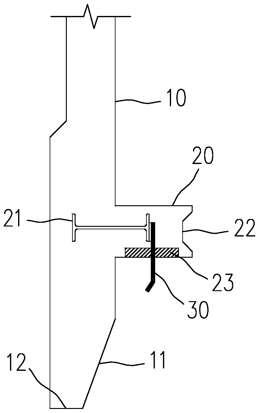
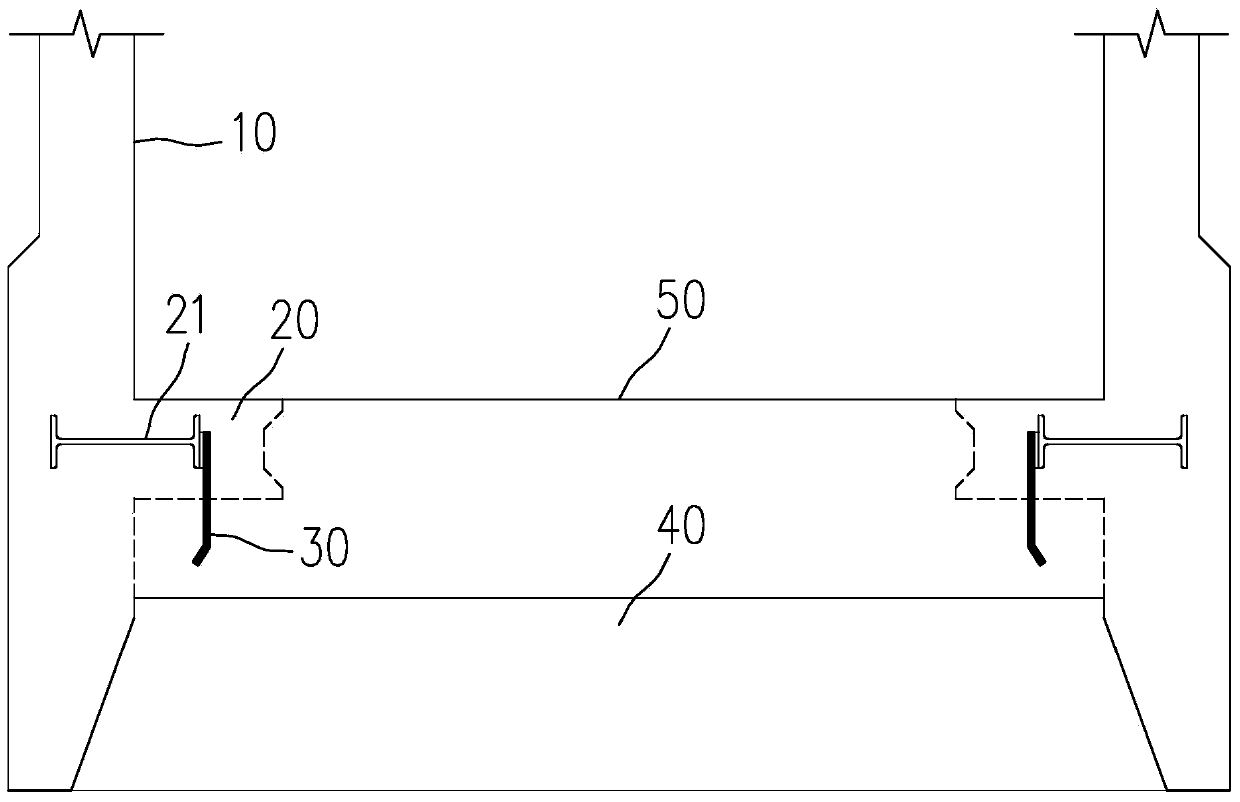
[0029] Such as figure 1 , 2 As shown, the inner well wall of the bottom caisson 10 is provided with several corbels 20 at the position where the bottom plate 50 is poured, and the corbels 20 are all along the radial plane of the bottom caisson 10 The inner side stretches flat; the corbel 20 is pre-embedded with a waterstop 30, one end of the waterstop 30 extends into the corbel 20 and is fixedly connected with the built-in steel plate 21 in the corbel 20, the waterstop The other end of 30 protrudes downward at the outside of corbel 20 , and one end of waterstop 30 protruding out of corbel 20 is bent toward the well wall side of bottom caisson 10 .

[0030] The end of one side of the corbel 20 extending horizontally to the inside of the bottom joint caisson 10 is provided with a post-casting groove 22 that is convenient for pouring the bottom plate 50, and the upper and lower ends of the post-casting groove 22 sink toward the bottom joint. The inner side of the well 10 is pro...

Embodiment 2

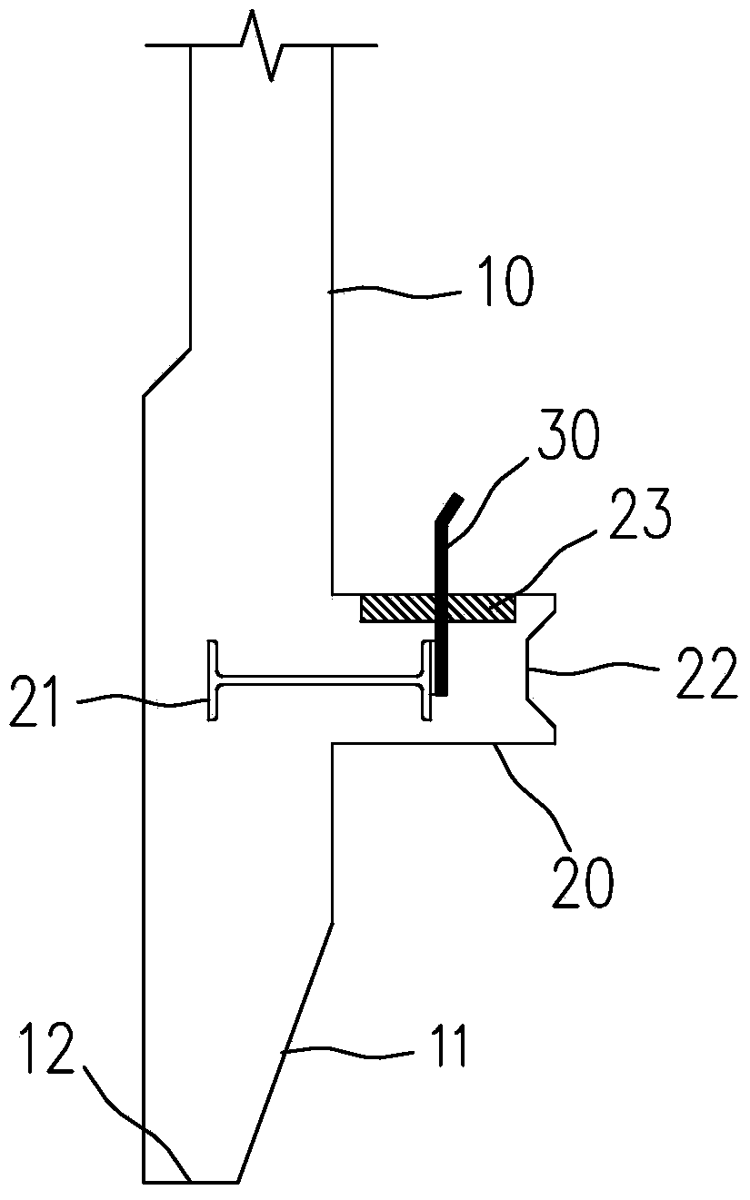
[0036] Such as figure 1 , 2 As shown, the inner well wall of the bottom caisson 10 is provided with several corbels 20 at the position where the bottom plate 50 is poured, and the corbels 20 are all along the radial plane of the bottom caisson 10 The inner side stretches flat; the corbel 20 is pre-embedded with a waterstop 30, one end of the waterstop 30 extends into the corbel 20 and is fixedly connected with the built-in steel plate 21 in the corbel 20, the waterstop The other end of the water stop 30 protrudes upwards outside the corbel 20 , and one end of the waterstop 30 protruding outside the corbel 20 is bent toward the inside of the bottom caisson 10 .

[0037] The end of one side of the corbel 20 extending horizontally to the inside of the bottom joint caisson 10 is provided with a post-casting groove 22 that is convenient for pouring the bottom plate 50, and the upper and lower ends of the post-casting groove 22 sink toward the bottom joint. The inner side of the w...


PUM


Abstract

The invention belongs to the technical field of building construction, and particularly relates to a base section sinking well with a waterproof structure. A plurality of protrusions are arranged on a cast base plate of a well wall inside the base section sinking well, the protrusions horizontally stretch towards the inner side of the base section sinking well along the radial plane of the base section sinking well, a waterstop is buried in the protrusions in advance, one end of the waterstop stretches into the protrusions and is fixedly connected with an internally-arranged steel plate in the protrusions, the other end o the waterstop stretches out of the outer sides of the protrusions, when the well wall of the sinking well and the base plate are cast for the second time, a bracket and the base plate are cast integrally, meanwhile, a waterstop on the bracket is also cast in the base plate, and due to the waterproof structure, the integrality of the bottom section sinking well and the base plate is greatly enhanced, and the waterproof effect of the base section sinking well and the base plate is greatly improved. Compared with an original sinking well structure, the base section sinking well with the waterproof structure is simple in structure, good in waterproof effect, and good in economical efficiency, and is easily cast and formed.

Description

technical field [0001] The invention belongs to the technical field of building construction, and in particular relates to a bottom caisson with a waterproof structure. Background technique [0002] During the design and construction process of the caisson structure, the bottom sealing is the last step. The connection between the caisson well wall and the bottom plate belongs to the secondary pouring during the bottom sealing. Due to the existence of construction joints, waterproof measures are particularly important. The general waterproof measure is to reserve grooves on the caisson well wall and inner partition wall, that is, the foundation groove. After the caisson reaches the design elevation, the bottom plate is poured in the groove after cleaning the groove. However, it is difficult to pour and tamp because of the secondary pouring. Dense, especially in the case of wet sealing, so the effect of waterproof measures for reserved grooves is not particularly ideal. Cont...

Claims


Application Information

Patent Timeline
Patent Type & Authority Applications(China)
IPC IPC(8): E02D23/00E02D31/02E02D29/16
Inventor 戴良军曾伟秦旭飞陈卫东刘晓晗崔林创
Owner ANHUI INST OF BUILDING RES & DESIGN
Why Eureka
Try Eureka