Butterfly valve structure

A butterfly valve and arc surface structure technology, applied in the field of butterfly valve structure, can solve the problem that the valve body cannot be integrated with pipeline control and filtration, and achieve the effect of convenient disassembly and maintenance

Active Publication Date: 2014-04-16
HEFEI BOE OPTOELECTRONICS TECH +1
View PDF9 Cites 0 Cited by
  • Summary
  • Abstract
  • Description
  • Claims
  • Application Information

AI Technical Summary

Problems solved by technology

[0004] Therefore, the existing butterfly valve cannot integrate the

Method used


Image

  • Butterfly valve structure
  • Butterfly valve structure
  • Butterfly valve structure

Examples


Example Embodiment

[0026] The specific embodiments of the present invention will be described in further detail below in conjunction with the drawings and embodiments. The following examples are used to illustrate the present invention, but not to limit the scope of the present invention.

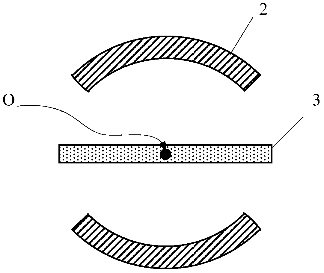
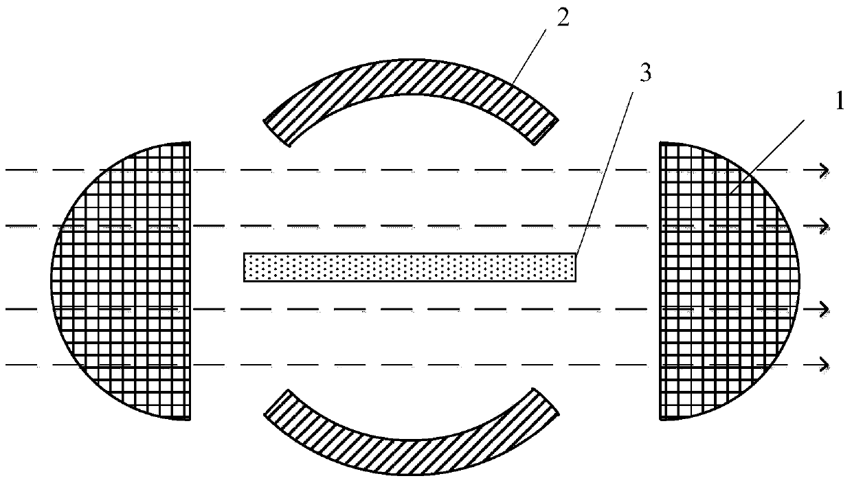
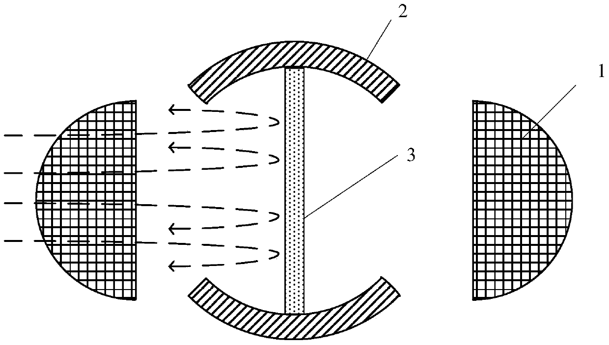
[0027] The embodiment of the present invention provides a butterfly valve structure, the structure diagram is as Figure 4 As shown, specifically including:

[0028] The valve body 2, the valve 3 and the filter screen. The valve 3 has a quarter spherical arc surface structure. The filter screen includes a first filter screen 11 and a second filter screen 12, both of which have a quarter spherical arc surface structure. And the connection mode of the first filter screen 11-the valve 3-the second filter screen 12 is adopted to form a valve structure, which is assembled in the valve body 2.

[0029] The butterfly valve structure changes the structure of the existing butterfly valve that does not include the filter scr...


PUM


Abstract

The invention discloses a butterfly valve structure comprising a valve body, a valve, and filter screens. The valve body is in a 1/4 spherical chamber structure. The filter screens include a first filter screen and a second filter screen both in 1/4 spherical chamber structures, and the first filter screen, the valve and the second filter screen are connected in sequence to form a valve structure fitted in the valve body. The butterfly valve structure is in the valve structure combining the filter screens and the valve; the first and second filter screens are mounted on two sides of the valve body to form the valve structure; when the valve structure closes, gas cannot pass through; when the valve structure opens, the gas passing through is filtered by the first and second filter screens; foreign matters such as glass fragments in the gas can be prevented from entering a mechanical pump through a pipeline; the butterfly valve structure is helpful for checking and replacing the valve and the filter screens and convenient for demounting and maintenance.

Description

technical field [0001] The invention relates to the field of display technology, in particular to a butterfly valve structure for controlling and filtering pipelines. Background technique [0002] Butterfly valve, also known as flap valve, is a regulating valve with simple structure, and it can also be used for switch control of low-pressure pipeline medium. Butterfly valve refers to a valve whose closing part (disc or butterfly plate) is a disc that rotates around the valve shaft to open and close. It mainly plays the role of cutting and throttling on the pipeline. The opening and closing part of the butterfly valve is a disc-shaped butterfly plate that rotates around its own axis in the valve body to achieve the purpose of opening and closing or adjustment. There is also a wafer butterfly valve, the butterfly plate of the wafer butterfly valve is installed in the diameter direction of the pipeline, and the valve is fully open. The wafer butterfly valve has simple structu...

Claims


Application Information

Patent Timeline
IPC IPC(8): F16K1/22F16K1/36F16K27/02
CPCF16K1/22F16K1/36F16K27/0218
Inventor 朱仁彬
Owner HEFEI BOE OPTOELECTRONICS TECH
Why Eureka
Try Eureka