
Combined substation

A substation and combined technology, applied in the field of substations, can solve the problems of bulky substations, inconvenient use, troublesome disassembly and maintenance, etc., and achieve the effects of improving corrosion resistance, ensuring safety, and facilitating disassembly and maintenance

Inactive Publication Date: 2018-04-13
浙江科诺电力发展有限公司
View PDF5 Cites 0 Cited by
  • Summary
  • Abstract
  • Description
  • Claims
  • Application Information

AI Technical Summary

Problems solved by technology

[0003] The substation is a place to change the voltage. In order to transmit the electric energy from the power plant to a distant place, the voltage must be raised to high-voltage electricity, and then the voltage is lowered as needed near the user. This work of raising and lowering the voltage It is completed by a substation. The main equipment of a substation is a switch and a transformer. According to the size, the small one is called a substation, and the substation is larger than a substation. The substation generally refers to a voltage level below one hundred and ten thousand volts. Step-down substations, substations include "boost and step-down" substations of various voltage levels, substations are power facilities that transform voltage, receive and distribute electric energy, control the flow of power and adjust voltage in the power system. The power grids of all levels of voltage are connected. In a specific environment, the substation converts AC-DC-AC, such as submarine power cables and long-distance transmission. Some use high-voltage direct current transmission and transformation. Capacitive reactance loss has energy-saving effect, but the existing substations are generally bulky, dismantled and troublesome for maintenance, which brings inconvenience to people's use. Therefore, we propose a combined substation

Method used


Image

  • Combined substation
  • Combined substation
  • Combined substation

Examples


Embodiment Construction

[0020] The following will clearly and completely describe the technical solutions in the embodiments of the present invention with reference to the accompanying drawings in the embodiments of the present invention. Obviously, the described embodiments are only some, not all, embodiments of the present invention. Based on the embodiments of the present invention, all other embodiments obtained by persons of ordinary skill in the art without making creative efforts belong to the protection scope of the present invention.

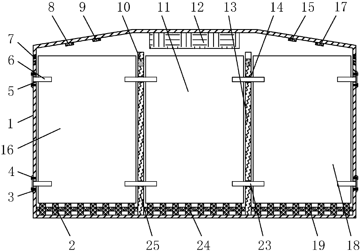
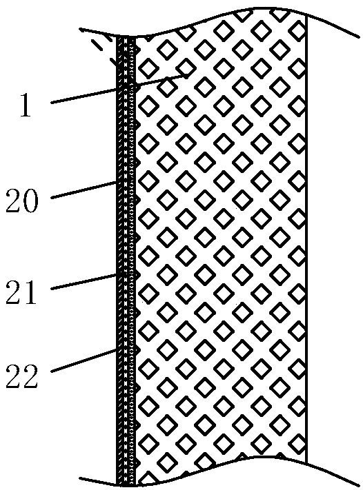
[0021] see Figure 1-3 , a combined substation, including a box body 1, the bottom of the box body 1 is fixedly connected with a rubber pad, the inner surface of the box body 1 is fixedly connected with an asbestos heat insulation layer, and the left end of the inner cavity of the box body 1 is fixedly installed with a first partition Plate 25, the right end of box body 1 cavity is fixedly installed with the second dividing plate 13, and the upper end of first...


PUM


Abstract

The invention discloses a combined substation. The combined substation comprises a box body, wherein a first partition plate is fixedly arranged at a left end of an inner cavity of the box body, a second partition plate is fixedly arranged at a right end of the inner cavity of the box body, line through holes are formed in upper ends of inner surfaces of the first partition plate and the second partition plate, first rollers are movably arranged at the bottom of a left side of the first partition plate and the bottom of a right side of the inner cavity of the box body, high-voltage switch equipment is movably connected with upper surfaces of the first rollers, and second rollers are movably arranged at the bottom of a right side of the first partition plate and the bottom of a left side ofthe second partition plate. In the combined substation, the first partition plate is fixedly arranged at the left end of the inner cavity of the box body, the second partition plate is fixedly arranged at the right end of the inner cavity of the box body, the high-voltage switch equipment is placed on the upper surfaces of the first rollers, a power distribution transformer is placed on upper surfaces of the second rollers, low-voltage power distribution equipment is placed on upper surfaces of third rollers, the combined installation demand of the substation is achieved, and people is convenient to disassemble and maintain the substation.

Description

technical field [0001] The invention relates to the technical field of substations, in particular to a combined substation. Background technique [0002] Electricity is an energy powered by electric energy. It was invented in the 1870s. The invention and application of electric power set off the second industrialization climax and became one of the three scientific and technological revolutions in the world since the eighteenth century in human history. It has changed people's lives. The large-scale power system that appeared in the 20th century is one of the most important achievements in the history of human engineering science. It is a power production and consumption system composed of power generation, power transmission, power transformation, power distribution and power consumption. , it converts the primary energy of nature into electricity through mechanical energy devices, and then supplies the electricity to various users through power transmission, transformation...

Claims


Application Information

Patent Timeline
IPC IPC(8): H02B7/06H02B1/56
CPCH02B7/06H02B1/565
Inventor 何昌文金圣伟叶文雷蔡宇超
Owner 浙江科诺电力发展有限公司
Learn More