Fixing device for electric power instrument

A fixed device, power and electrical technology, applied in the direction of instruments, instrument parts, casings, etc., can solve the problems of inability to dissipate heat from the condensing tube to the instrument, and the inability of fans to dissipate heat from it, achieving wide applicability, avoiding shaking, and easy disassembly. and maintenance effect

Pending Publication Date: 2020-03-06
天门市天成智能科技有限公司
View PDF1 Cites 0 Cited by
  • Summary
  • Abstract
  • Description
  • Claims
  • Application Information

AI Technical Summary

Problems solved by technology

The instruments and meters in the above-mentioned patents have the following disadvantages: the instrument panel needs to be portable, and the condensing device needs to be connected to the

Method used


Image

  • Fixing device for electric power instrument
  • Fixing device for electric power instrument
  • Fixing device for electric power instrument

Examples


Example Embodiment

[0025] Example 1

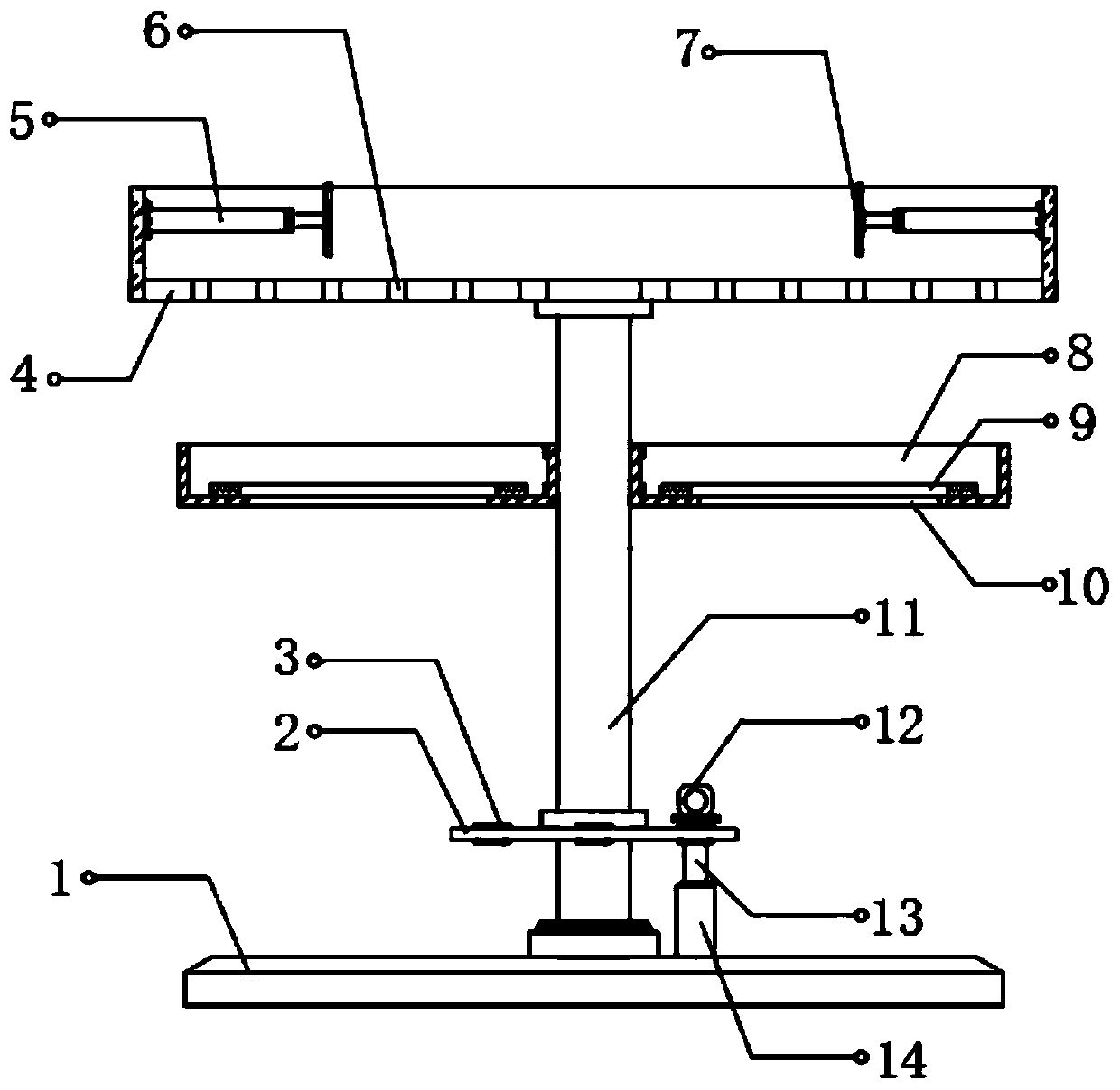
[0026] refer to Figure 1-2 , a fixing device for electric and electrical instruments, comprising a base 1, the middle position of the top of the base 1 is rotatably connected with a support 11 through bearings, and the top of the support 11 is fixedly connected with a fixed box 4, and the bottom of the fixed box 4 is provided with evenly distributed through holes 6, and the inner walls on both sides of the fixed box 4 are connected with electric push rods 5 by bolts, and the side where the two electric push rods 5 are close to each other is fixedly connected with the main push plate 7, and both sides of the top of the pillar 11 pass through The bolts are connected with the fan box 8, the electrical instrument is placed inside the fixed box 4, the two electric push rods 5 are pushed inward, and the electrical instrument is clamped and fixed by the two main push plates 7, and the fan heaters are respectively placed inside the two fan boxes 8. Fan, after the ...

Example Embodiment

[0032] Example 2

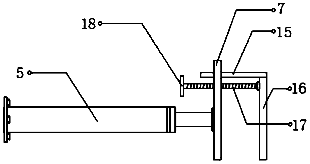
[0033] refer to image 3 , a kind of fixing device for electric power instrument, present embodiment is compared with embodiment 1, and the top thread of main push plate 7 is connected with screw rod 17, and one end of screw rod 17 is connected with auxiliary push plate 16 through bearing rotation, the other end of screw rod 17 One end is threadedly connected with a knob 18 , the top of the auxiliary push plate 16 is welded with a limit rod 15 , and one end of the limit rod 15 is inserted into the top of the main push plate 7 .

[0034] Working principle: first send the auxiliary push plate 16 to the side of the electrical instrument through the electric push rod 5, then turn the screw 17 through the knob 18, and use the auxiliary push plate 16 to finally clamp the electrical instrument to avoid excessive push of the electric push rod 5 Damage electrical instrument, in the process that auxiliary push pedal 16 is adjusted, stop bar 15 is at the top synchrono...


PUM


Abstract

The invention discloses a fixing device for an electric power instrument. The fixing device for the electric power instrument comprises a bottom seat, wherein a support pillar is rotatably connected with the middle position of the top of the bottom seat through a bearing, a fixed box is fixedly connected with the top of the support pillar, through holes evenly distributed are formed in the bottomof the fixed box, and electric push rods are connected with inner walls of two sides of the fixed box through bolts. When the fixing device for the electric power instrument is used, the electric power instrument is placed in the fixed box, the two electric push rods push the electric power instrument inwards, the electric power instrument is clamped and fixed through two main push plates, heat dissipation air fans are respectively placed in two fan boxes, the air fans blow airstream upwards after electrified, the airstream performs heat dissipation on the electric power instrument through thethrough holes in the bottom of the fixed box, the overheating circumstance is prevented from occurring in long time work of the electric power instrument, the fan boxes can fix the air fans on the heat dissipation position, the air fans are convenient to dismount and maintain, and two rubber rings achieve a protection and buffering function for the air fans, and prevent the air fans from being damaged due to collision generated when the air fans are placed in the fan boxes.

Description

technical field [0001] The invention relates to the technical field of electrical engineering, in particular to a fixing device for electric power meters. Background technique [0002] At present, power meters are power measurement and control equipment that provide solutions for power parameter measurement, power quality monitoring and analysis, and electrical equipment control. As an advanced intelligent and digital front-end acquisition component of the power grid, power meters have been widely used in various control systems, substation automation, community power monitoring, switch cabinets and other equipment. features. [0003] After retrieval, the Chinese patent application number is CN201720978832.X, which discloses a fixed placement device for instruments and meters, including a fixed placement table, a mounting groove, a supporting steel frame and a fixed column. The instruments and meters in the above-mentioned patents have the following disadvantages: the inst...

Claims


Application Information

Patent Timeline
IPC IPC(8): G12B9/10
CPCG12B9/10
Inventor 赖郁盛
Owner 天门市天成智能科技有限公司
Why Eureka
Try Eureka