Forced sealing ball valve

A technology of forced sealing and ball valves, applied in valve details, valve devices, valve operation/release devices, etc., can solve the problems of difficult micro-leakage control, affecting the service life of valves, and many leakage control points, so as to save resources, Simple structure and low opening and closing torque

Active Publication Date: 2014-04-16
JIANGSU QUANHANG VALVE CO LTD
View PDF6 Cites 12 Cited by
  • Summary
  • Abstract
  • Description
  • Claims
  • Application Information

AI Technical Summary

Problems solved by technology

[0002] A ball valve is a valve with a sphere as a closing member. It has the advantages of small flow resistance, no damage to the shape of the fluid, and convenient switching. However, the wear between the sphere and the valve seat during switching is also a major problem It seriously affects the service life of valves, and researchers in the valve industry have also done a lot of work for this, such as a "low torque non-wearing fixed ball valve" disclosed in Chinese invention patent CN201310323798. There is also a significant improvement in performance, specifically manifested in the rotation of the ball valve when the ball valve is opened and closed. The ball completes the 90° rotation action relative to the valve seat under the condition of small specific pressure, so it is called "low torque non-wear fixed ball valve". , but the fly in the ointment is: the sealing specific pressure between the valve seat and the ball is realized by converting the hydraulic energy of the hydraulic system into mechanical energy, so there are many leakage control points, especially the micro-leakage control is difficult. When used under high-pressure conditions, a lot of cumbersome devices need to be added to ensure the working performance of the hydraulic system within the allowable temperature range, and the manufacturing cost is relatively high

Method used


Image

  • Forced sealing ball valve
  • Forced sealing ball valve
  • Forced sealing ball valve

Examples


Embodiment Construction

[0032] The present invention will be further described below in conjunction with accompanying drawing and specific embodiment:

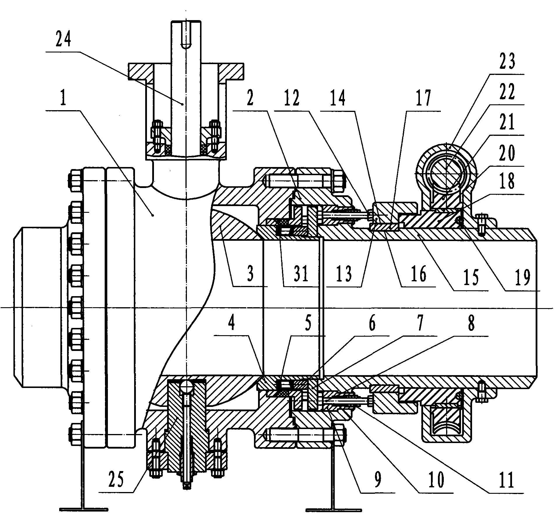
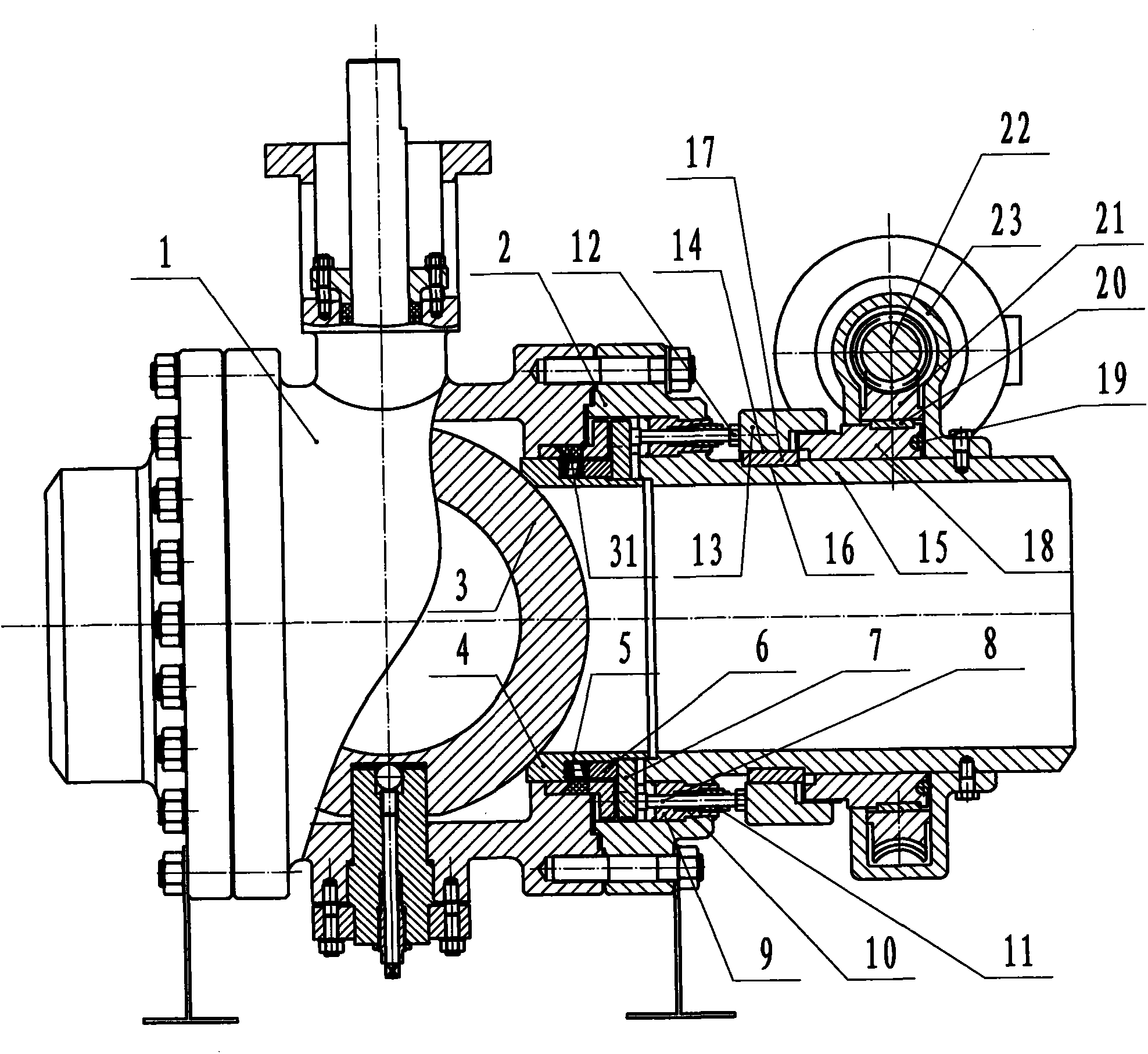
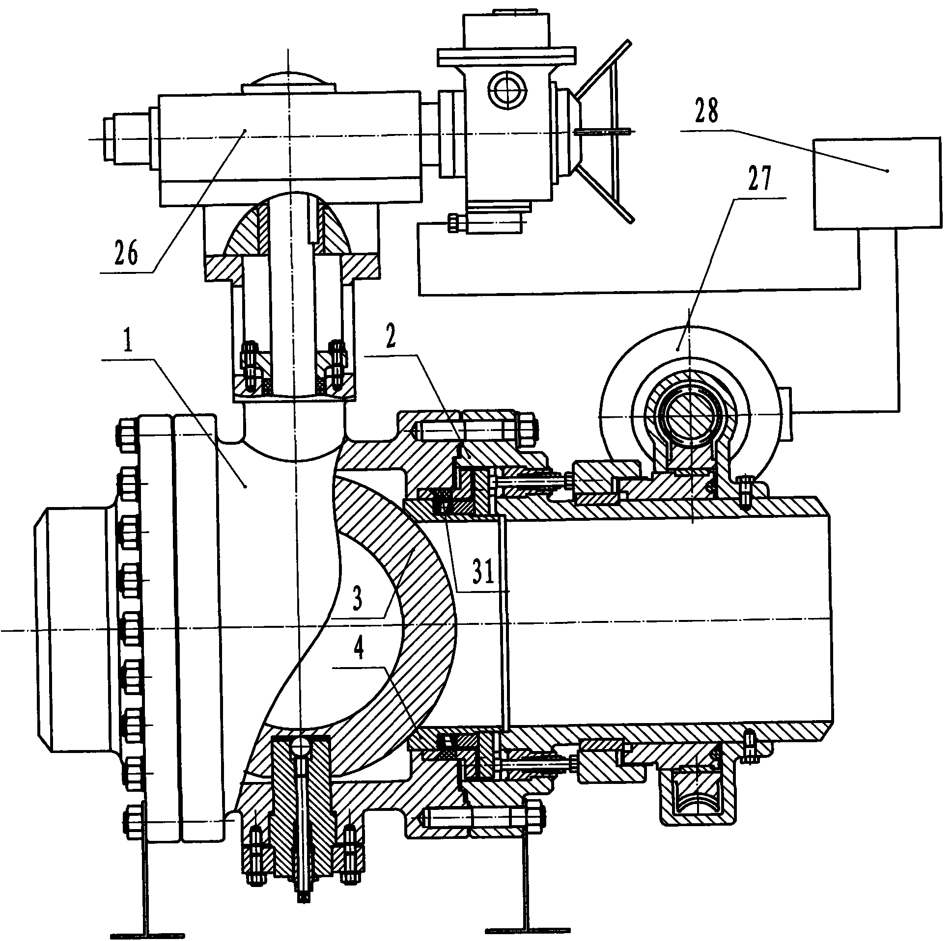
[0033] Such as figure 1 Shown is a schematic structural diagram of the open state of the first embodiment of the present invention, which includes a valve body 1, an auxiliary valve body 2, an upper valve stem 24, a lower valve stem 25, an electric actuator 26, a ball 3 with a flow channel, and a valve seat 4. Valve seat packing 31, the outer side of the valve seat 4 has a pressure transmission system connected to the stud nut driven forced sealing device 27 installed on the outer circle of the auxiliary valve body fluid pipeline 15, the pressure transmission system is: The back of the valve seat has several closed holes arranged in a circle, and springs 5 ​​are placed in the closed holes, and a plunger 6 matched with the closed hole is placed on the outside of the spring 5, and the outer end of the plunger 6 and the force transmission plate 7 Conne...


PUM


Abstract

The invention discloses a ball valve, and particularly relates to a forced sealing ball valve. The forced sealing ball valve comprises a valve body, an auxiliary valve body, a ball body, a valve seat and an auxiliary valve body fluid pipeline. A stud-nut driving type forced sealing device is arranged on the outer circle of the auxiliary valve body fluid pipeline, wherein a worm wheel and a driving stud are connected through a flat key. When the driving stud rotates, an axial sliding key groove of a driven nut screwed with the driving stud is made to conduct axial linear motion along a guiding key on the auxiliary valve body fluid pipeline, so that the needed sealing specific pressure is produced between the valve seat and the ball body in a valve cavity through the pressure produced outside via the pressure transferring. Thus, low-torque opening and closing and forced sealing are achieved. Related motion processes of the stud-nut driving type forced sealing device and an electric actuator are achieved through an automatic control system in the opening and closing process and the sealing process. According to the structure of the forced sealing ball valve, the selected corresponding materials can be suitable for various severe fluid and environments.

Description

technical field [0001] The invention relates to a valve, in particular to a forced sealing ball valve. Background technique [0002] A ball valve is a valve with a sphere as a closing member. It has the advantages of small flow resistance, no damage to the shape of the fluid, and convenient switching. However, the wear between the sphere and the valve seat during switching is also a major problem It seriously affects the service life of valves, and researchers in the valve industry have also done a lot of work for this, such as a "low torque non-wearing fixed ball valve" disclosed in Chinese invention patent CN201310323798. There is also a significant improvement in performance, specifically manifested in the rotation of the ball valve when the ball valve is opened and closed. The ball completes the 90° rotation action relative to the valve seat under the condition of small specific pressure, so it is called "low torque non-wear fixed ball valve". , but the fly in the ointm...

Claims


Application Information

Patent Timeline
Patent Type & Authority Applications(China)
IPC IPC(8): F16K5/06F16K5/08F16K31/04
CPCF16K5/0689F16K5/201F16K31/043F16K31/53
Inventor 郝思宏
Owner JIANGSU QUANHANG VALVE CO LTD
Why Eureka
Try Eureka