Delay pulse Raman amplification based distributed sensing system

A Raman amplification and sensing system technology, which is applied in the direction of transmitting sensing components with optical devices, can solve the problems of limiting sensing distance, self-phase modulation, reducing signal-to-noise ratio, etc., to extend the sensing distance and ensure coherence Sexual and non-linear cumulative effects are small

Active Publication Date: 2014-04-16
UNIV OF ELECTRONICS SCI & TECH OF CHINA
View PDF7 Cites 9 Cited by
  • Summary
  • Abstract
  • Description
  • Claims
  • Application Information

AI Technical Summary

Problems solved by technology

In order to extend the sensing distance and improve the sensitivity, the existing distributed sensing system generally adopts the method of increasing the Raman pump power, but simply increasing the Raman pump power may easily cause abnormalities such as self-phase modulation and modulation instability. The generation of linear effect, which reduces the signal-to-noise ratio and limits the sensing distance

Method used


Image

  • Delay pulse Raman amplification based distributed sensing system
  • Delay pulse Raman amplification based distributed sensing system
  • Delay pulse Raman amplification based distributed sensing system

Examples


Embodiment

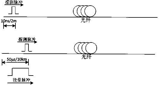
[0031] In order to illustrate the nonlinear effect caused by increasing the pump power more specifically, take a 50km G.652 optical fiber as an example. Because pulses of different wavelengths are transmitted at different speeds in the fiber, the 1550nm probe light and the 1455nm pump light have a group velocity mismatch. This characteristic leads to the walk-off phenomenon. The dispersion parameter is: ≈ , therefore, for the faster pump pulse to interact with the slower probe pulse, it is necessary to ensure that there is a certain delay in the pump pulse. Taking the time delay of 10ns as an example, the pump pulse will undergo stimulated Raman scattering with the detection pulse at 10km, thereby amplifying the detection optical signal. Such as figure 2 Shown is a schematic diagram of the interaction of the pump pulse with the amount of time delay with the probe pulse.

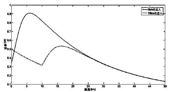
[0032] In order to further illustrate that the distributed sensing system based on delayed pulse Raman...


PUM


Abstract

The invention discloses a delay pulse Raman amplification based distributed sensing system. The delay pulse Raman amplification based distributed sensing system comprises a narrow line width light source, a Raman pump light source, a first modulation module and a second modulation module; the first modulation module is connected with the narrow line width light source; the second modulation module is connected with the Raman pump light source; the first modulation module passes through an erbium-doped fiber amplifier and a circulator in turn to be connected with a wavelength division multiplexer; the second modulation module is connected with the wavelength division multiplexer directly; the wavelength division multiplexer is connected with a sensing fiber; the first modulation module is connected with the second modulation module through a signal generator; the circulator is connected with a detector, a data acquisition module and a computer in turn through a filter. According to the delay pulse Raman amplification based distributed sensing system, the long effective sensing distance of the detection light can be achieved through the pulse modulation pumped Raman amplification with a certain amount of time delay.

Description

technical field [0001] The invention relates to the technical field of optical fiber sensing, in particular to a distributed sensing system based on time-delayed pulse Raman amplification. Background technique [0002] With the development of society, people's dependence on information is becoming more and more serious, and the demand for information transmission is rapidly expanding. The capacity of existing optical fiber systems has been greatly increased, and the simple transmission distance of non-electric regenerative relay has been increased. hotspot. In this context, Raman amplifiers have attracted extensive attention due to their inherent low-noise and wide-bandwidth characteristics. [0003] The so-called Raman amplification is to transfer a part of the incident light power to the Stokes wave with a lower frequency than it. If a weak signal wave and a strong pump light wave are transmitted in the optical fiber at the same time, and the weak signal wavelength is pla...

Claims


Application Information

Patent Timeline
Patent Type & Authority Applications(China)
IPC IPC(8): G01D5/36
Inventor 王子南黎进范孟秋饶云江
Owner UNIV OF ELECTRONICS SCI & TECH OF CHINA
Why Eureka
Try Eureka