Visual minitype fluid cavitation testing device

A test device and cavitation technology, which is applied in the field of aerospace and refrigeration cryogenic engineering, can solve the problems of large cryogenic fluid, unsuitable miniaturized experimental research, complex structure, etc., and achieve stable performance, good heat insulation effect, and low cost.

Inactive Publication Date: 2014-04-16
ZHEJIANG UNIV
View PDF2 Cites 16 Cited by
  • Summary
  • Abstract
  • Description
  • Claims
  • Application Information

AI Technical Summary

Problems solved by technology

The experimental device uses a large-diameter flow channel and a cryogenic pump to form a closed loop with a complex structure and

Method used


Image

  • Visual minitype fluid cavitation testing device

Examples


Embodiment Construction

[0031] The following is a detailed description of the visualized small-scale fluid cavitation testing device of the present invention in conjunction with the accompanying drawings.

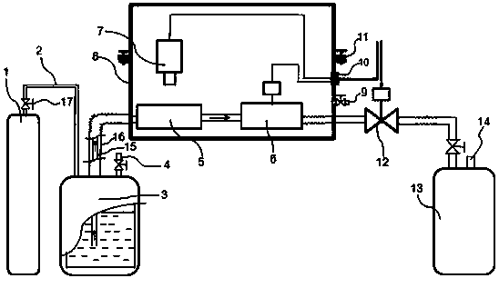
[0032] Such as figure 1 Shown is the visualized small fluid cavitation test device of the present invention, in the figure, the high-pressure gas tank 1 communicates with the test medium storage tank 3 through the air guide tube 2, and the test medium storage tank 3 communicates with the cavitation component 5 through the infusion tube 15, and the steam Corrosion part 5 is communicated with flowmeter 6 by the pipeline of horizontal placement, and flowmeter 6 is connected with the recovery bottle 13 in the recovery unit by pipeline;

[0033] In order to ensure the stability and controllability of the low-temperature liquid pressure source, preferably, a high-pressure gas tank 1 with a valve 17 is used as the pressure source.

[0034] One end of the infusion tube 15 communicates with the cavitation...


PUM


Abstract

The invention discloses a visual minitype fluid cavitation testing device. The visual minitype fluid cavitation testing device comprises a visual testing unit and a feed liquid unit for providing a test medium for the visual testing unit, wherein the visual testing unit comprises a vacuum chamber, a cavitation part, a camera and a flowmeter, wherein the cavitation part is positioned in the vacuum chamber, and the camera is positioned in the vacuum chamber and is used for collecting a real-time image in the cavitation part; the flowmeter is positioned in the vacuum chamber and is used for collecting the flow of a test medium; the feed liquid unit comprises a test medium storage tank, a pressure source, an air guiding piece communicated between the test medium storage tank and the pressure source as well as an infusion pipe communicated between the test medium storage tank and the cavitation part. The visual minitype fluid cavitation testing device provided by the invention has the advantages that the structure is simple, a heat insulation effect is good, the property is stable, the test data are exact, the cost is low, and the visual minitype fluid cavitation testing device is used for an experimenter in a common laboratory.

Description

technical field [0001] The invention relates to the technical field of aerospace and refrigeration low-temperature engineering, in particular to a visualized small-scale low-temperature cavitation test device. Background technique [0002] In the field of aerospace, liquid oxygen and liquid hydrogen are considered to be ideal fuels for rocket launches, but when they flow in mechanical parts, vaporization occurs in some areas due to pressure reduction to near or below the saturation pressure corresponding to the temperature, said For cavitation phenomenon. [0003] The Venturi tube has the characteristics that the outlet pressure changes within a certain range and the fluid flow rate is almost constant, so it is used to precisely control the flow rate of liquid hydrogen / liquid oxygen in a high-thrust rocket engine system. At the venturi throat, fluid cavitation occurs due to the static pressure being lower than the saturation pressure corresponding to the temperature. Unlik...

Claims


Application Information

Patent Timeline
IPC IPC(8): G01N3/56
Inventor 张小斌朱佳凯张伟熊炜陈建业
Owner ZHEJIANG UNIV
Why Eureka
Try Eureka