Arm frame control method, equipment and system and engineering machine

A control method and technology for controlling equipment, applied in the direction of using feedback control, etc., can solve problems such as frequent booms, affecting the operation of the boom, and inability to effectively control the boom

Active Publication Date: 2014-04-16
ZOOMLION HEAVY IND CO LTD
View PDF7 Cites 17 Cited by
  • Summary
  • Abstract
  • Description
  • Claims
  • Application Information

AI Technical Summary

Problems solved by technology

[0004] However, the above-mentioned patents have poor practicability in the actual construction process of concrete pump trucks, mainly reflected in:
[0005] 1): There must be obstacles to limit the distribution range of the concrete pump truck, and the distribution range of the boom cannot be limited for spaces without obstacles;
[0006] 2): The safety distance required by different obstacles is not the same. For example, the safety distance required by high-voltage lines is much greater than that of ordinary obstacles, but the distance measuring device of the above patent cannot effectively identify the difference between obstacles, and it cannot effectively control the boom Stay within a safe range in real time;
[0007] 3): When the working environment is very complicated, for example, there are a large number of changing obstacles near the boom, such as walking people, irregular objects on the construction site such as steel bars, etc., and the vibration of the boom, etc. will seriously interfere with the ranging results;
[0008] 4): When the distance between the boom and the obstacle is less than or equal to the preset safety distance, the boom control device will adjust the position of the boom to make the distance between the boom and the obstacle greater than the preset safety distance , but because the distance measurement results are affected by various factors, this will lead to frequent and disorderly adjustments of the boom, seriously affecting the operation of the boom and even causing safety accidents

Method used


Image

  • Arm frame control method, equipment and system and engineering machine
  • Arm frame control method, equipment and system and engineering machine
  • Arm frame control method, equipment and system and engineering machine

Examples


Embodiment Construction

[0033] Specific embodiments of the present invention will be described in detail below in conjunction with the accompanying drawings. It should be understood that the specific embodiments described here are only used to illustrate and explain the present invention, and are not intended to limit the present invention.

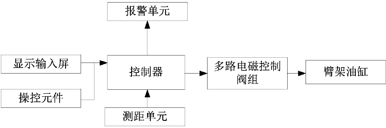
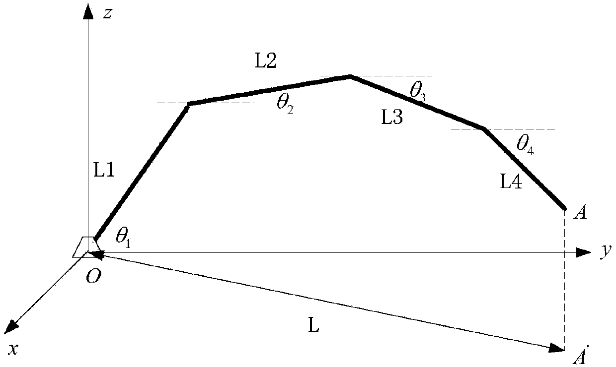
[0034] In the present invention, unless stated to the contrary, the used orientation words such as "up, down, top, bottom" generally refer to the directions shown in the drawings or refer to the vertical, perpendicular or gravitational directions The terms used to describe the mutual positional relationship of the various components mentioned above. In addition, in the three-dimensional coordinate system established in the present invention, the height direction of the boom is the z direction, the rotation plane of the boom is the xy plane, and the coordinate origin O is set as the hinge point between the boom and the turntable.

[0035] Such as figure 2 As s...


PUM


Abstract

The invention discloses an arm frame control method, equipment and system and an engineering machine. The control method includes the steps that the gyration center position and the gyration angle of an arm frame and inclination angles and extend lengths of all arm sections are received; the extend length of the arm frame is calculated according to the inclination angles and the extend lengths of all the arm sections; the tail end position of the arm frame is determined according to the gyration center position, the extend length and the gyration angle; according to the tail end position, the gyration center position and the allowable operating range of the arm frame, the maximum extend length Lmax of the arm frame at the current gyration angle and the gyration angle range, from alpha1 to alpha 2, of the arm frame gyrating under the condition of keeping the current arm extending posture are determined; according to the maximum extend length Lmax and the gyration angle range from alpha1 to alpha 2, the arm frame is manipulated to work in the allowable operating range.

Description

technical field [0001] The invention relates to the field of engineering machinery, in particular to a control method for controlling a boom, a control device, a control system and an engineering machinery including the system. Background technique [0002] Construction machinery with a boom system, such as concrete pump trucks, jetting machines, and distribution machines, etc., control the position of the end of the boom through the retraction and rotation of the boom, so as to realize the construction of the specified position. However, in many construction sites, due to the limited scope of work, it is difficult for the boom to move freely. For example, in tunnels, roadways and indoors, the boom cannot touch the wall, otherwise it will cause damage to the boom or even a safety accident; another example is some bridges. Surfaces, floors, etc., the jib must not exceed the boundary during operation, otherwise it will cause waste of materials; there are also some construction...

Claims


Application Information

Patent Timeline
Patent Type & Authority Applications(China)
IPC IPC(8): G05D3/12
Inventor 易伟春尹君万梁罗前星
Owner ZOOMLION HEAVY IND CO LTD
Why Eureka
Try Eureka