
Touch device and image acquisition device

An image capture device, optical touch technology, applied in the fields of instruments, electrical digital data processing, data processing input/output process, etc.

Inactive Publication Date: 2014-04-16
PIXART IMAGING INC
View PDF3 Cites 4 Cited by
  • Summary
  • Abstract
  • Description
  • Claims
  • Application Information

AI Technical Summary

Problems solved by technology

The substrate has an operating surface

Method used


Image

  • Touch device and image acquisition device
  • Touch device and image acquisition device
  • Touch device and image acquisition device

Examples


Embodiment Construction

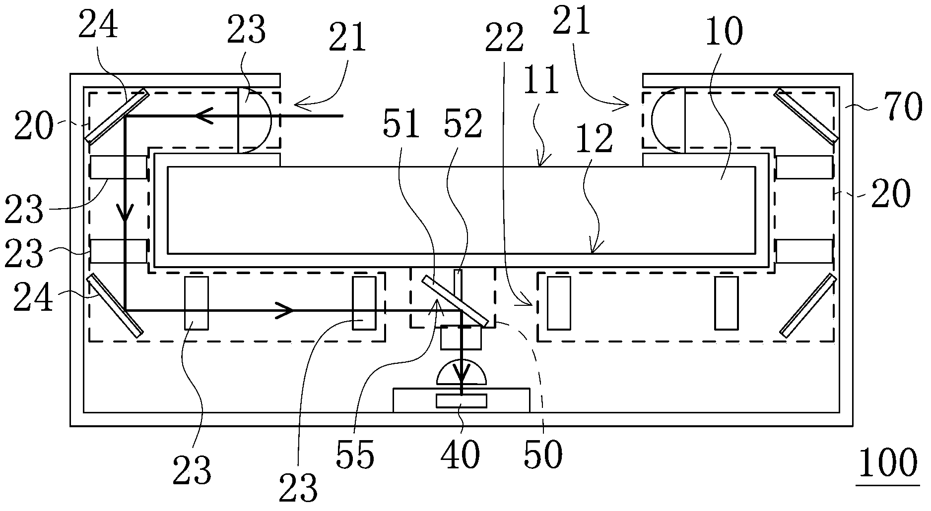
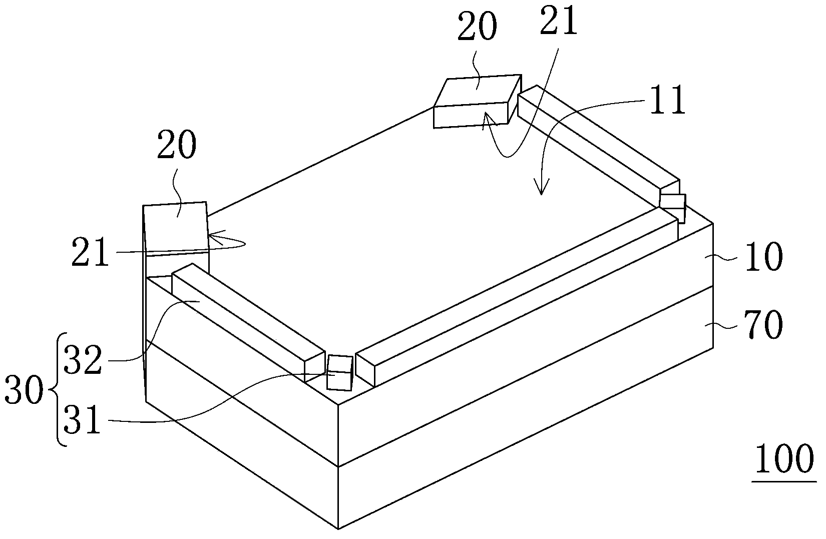
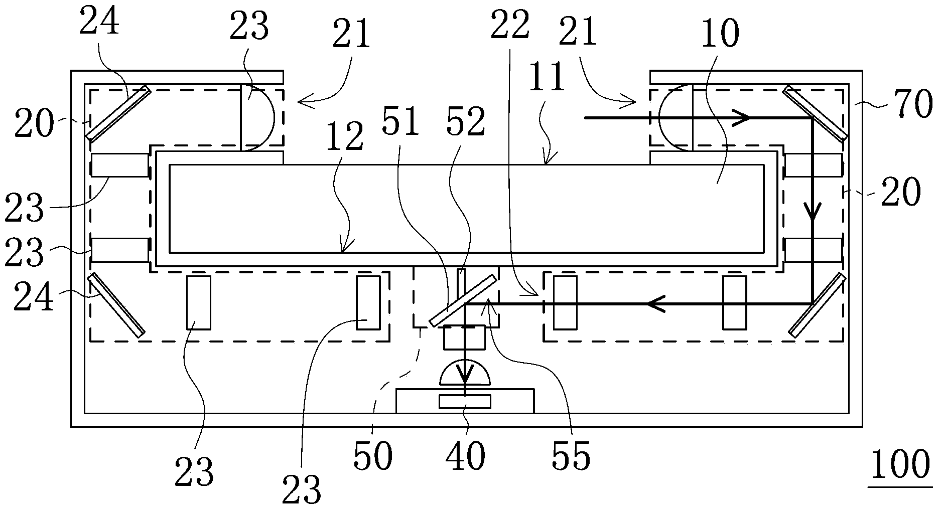
[0041] figure 1 It is a schematic cross-sectional view of an optical touch device 100 according to an embodiment of the present invention. As shown in the figure, the optical touch device 100 includes a substrate 10 , several imaging mirror groups (the part surrounded by the dotted line in the figure) 20 , a light detection unit 40 , and an optical path switching unit 50 .

[0042] Such as figure 1 As shown, the substrate 10 has an operation surface 11 for objects (such as fingers or pens) to touch or slide, and a back surface 12 opposite to the operation surface 11 . In this embodiment, the substrate 10 may be various types of display panels, such as liquid crystal display panels, but the present invention is not limited thereto. The substrate 10 can also be a plate without display function, such as a glass substrate, a plastic substrate, etc., but not limited thereto.

[0043] Each imaging lens group 20 has a light input end 21 and a light output end 22 . The light input...


PUM


Abstract

The invention provides an optical touch device and an image acquisition device. The optical touch device comprises a substrate, a plurality of image acquisition lens sets, a light detection unit and a light path switchover unit, wherein the substrate is provided with an operating surface, each image acquisition lens set is provided with a light input end and a light output end, the light input ends are located at the periphery of the substrate and used for obtaining light information on the operating surface, the light output ends are used for outputting light information, and the light path switchover unit is located between the light output ends and the light detection unit and used for transmitting the light information output by the light output ends to the light detection unit by turn.

Description

technical field [0001] The present invention relates to a touch device and an image capture device, and in particular to an optical touch device and an image capture device with several imaging mirror groups. Background technique [0002] The touch function has become one of the important functions of the current electronic devices. Currently, the touch modules used to provide the touch function include resistive, capacitive, and optical types. The electronic device can adopt different touch modules according to actual requirements. [0003] The optical touch module uses an optical detector to detect the position of the touch point. The user does not need to apply pressure to the screen, but only needs to touch or approach the screen lightly to be detected by the detector. Optical touch modules generally have several infrared light sources and photodetectors arranged at different positions around the module. The infrared light source emits infrared light to the target spac...

Claims


Application Information

Patent Timeline
Patent Type & Authority Applications(China)
IPC IPC(8): G06F3/042
Inventor 郑信基
Owner PIXART IMAGING INC
Learn More