Supercharge Your Innovation With Domain-Expert AI Agents!

Feedforward circuit to prevent reverse phase

A feedforward circuit and reverse-phase technology, applied in the field of feedforward circuits, can solve problems such as temporary changes in output voltage

Active Publication Date: 2017-01-04
ANALOG DEVICES INC
View PDF3 Cites 0 Cited by
  • Summary
  • Abstract
  • Description
  • Claims
  • Application Information

AI Technical Summary

Problems solved by technology

This condition can lead to saturation of the NPN BJT, which in turn can cause the output voltage to temporarily change in the wrong direction (i.e., reverse phase)
This problem is exacerbated when the input signal changes at high frequency and / or when the input stage has a low rise time

Method used


Image

  • Feedforward circuit to prevent reverse phase
  • Feedforward circuit to prevent reverse phase
  • Feedforward circuit to prevent reverse phase

Examples


Embodiment Construction

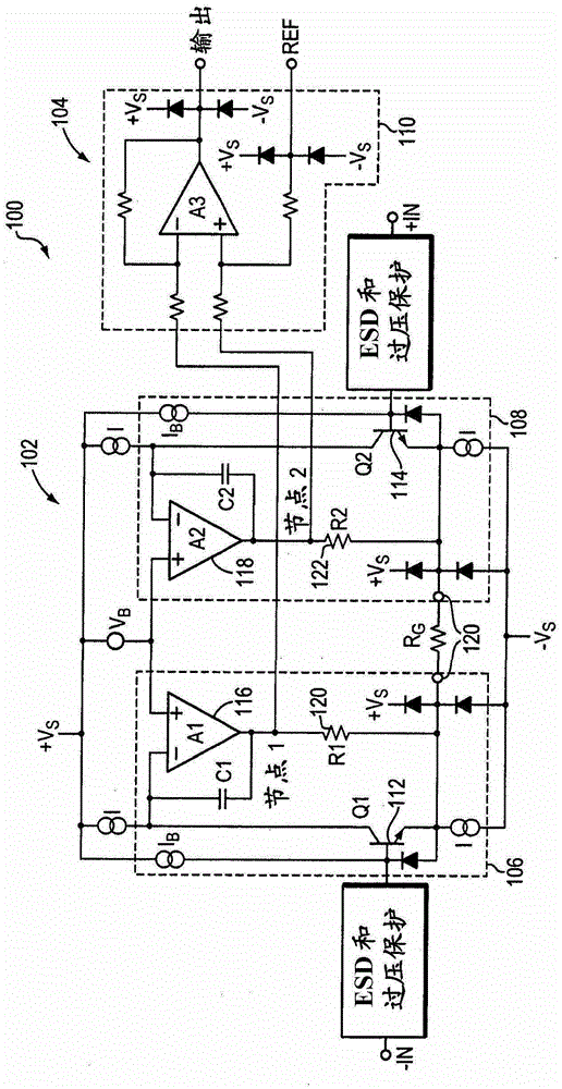
[0019] Figure 1A illustrates a conventional instrumentation amplifier 100 comprising two stages 102, 104: a first stage 102 comprising preamplifiers 106, 108 to provide differential amplification of the differential input signal +IN, -IN; and a second stage 104, which includes a differential amplifier 110 to provide a single-ended output signal OUTPUT. The differential amplifier 110 removes some or all of the common-mode voltage of the outputs of the preamplifiers 106 , 108 so that only the differential-mode signal is output by the second stage 104 .

[0020] In one embodiment of the invention, the preamplifiers 106, 108 are precision current feedback amplifiers. Because the input transistors 112 and 114 are biased with a fixed current, any input signal will force the output voltage of the amplifiers 116, 118 to change accordingly. The differential signal applied to the input is across resistor R G Pin 120 repeats; pass R G A current of is passed through resistors 120, 122 ...


PUM


Abstract

An amplifier includes a bootstrap circuit for improving the linearity of the amplifier and a feedforward circuit for adjusting a voltage of the bootstrap circuit in response to changes in an input signal. Use a feedforward circuit to adjust the voltage to prevent reverse phase conditions of the amplifier.

Description

technical field [0001] Embodiments of the present invention relate generally to amplifiers and, in particular, to feedforward circuits for amplifiers that prevent phase reversal. Background technique [0002] An amplifier is a device that takes an input signal, such as a voltage or current, and generates an output signal based on it. For example, as a general type of amplifier, a differential amplifier takes positive and negative versions of an input signal (ie, a differential input signal) and produces an amplified output signal based on the voltage difference between the two input versions. [0003] Conventionally, a bootstrap circuit includes various electronic components, such as resistors or transistors, that prevent changes in the base-emitter voltage caused by changes in the collector-base voltage of the amplifier's input transistors. The logarithmic change is used to improve the linearity of the amplifier. In this example, a unity-gain bootstrap circuit implemented...

Claims


Application Information

Patent Timeline
Patent Type & Authority Patents(China)
IPC IPC(8): H03F1/30
CPCH03F1/3211H03F1/52H03F3/45085H03F3/45103H03F2203/45682H03F3/45174
Inventor M·格斯滕哈伯D·F·鲍尔斯O·B·奇尔考C·C·特朗
Owner ANALOG DEVICES INC
Features
  • R&D
  • Intellectual Property
  • Life Sciences
  • Materials
  • Tech Scout
  • Unparalleled Data Quality
  • Higher Quality Content
  • 60% Fewer Hallucinations
Learn More