Apparatus for treating molten atomic reactor fuel rod using vertical cavity

A nuclear reactor, vertical cavity technology, used in reactors, nuclear engineering, nuclear power generation, etc., can solve problems such as the allowable cooling capacity limit, sudden steam generation, etc., to reduce energy, prevent radioactive pollution, and prevent radiation from leaking into the surrounding environment. Effect

Inactive Publication Date: 2014-04-16
昌股能世公司
View PDF7 Cites 4 Cited by
  • Summary
  • Abstract
  • Description
  • Claims
  • Application Information

AI Technical Summary

Problems solved by technology

The cooling equipment has the problem that the high temperature molten fuel rods and the coolant directly react with each other in the closed space, thereby causing the sudden generation of s

Method used


Image

  • Apparatus for treating molten atomic reactor fuel rod using vertical cavity
  • Apparatus for treating molten atomic reactor fuel rod using vertical cavity
  • Apparatus for treating molten atomic reactor fuel rod using vertical cavity

Examples


Embodiment Construction

[0023] Hereinafter, exemplary embodiments of the present invention will be described with reference to the accompanying drawings so as to be easily implemented by those skilled in the art.

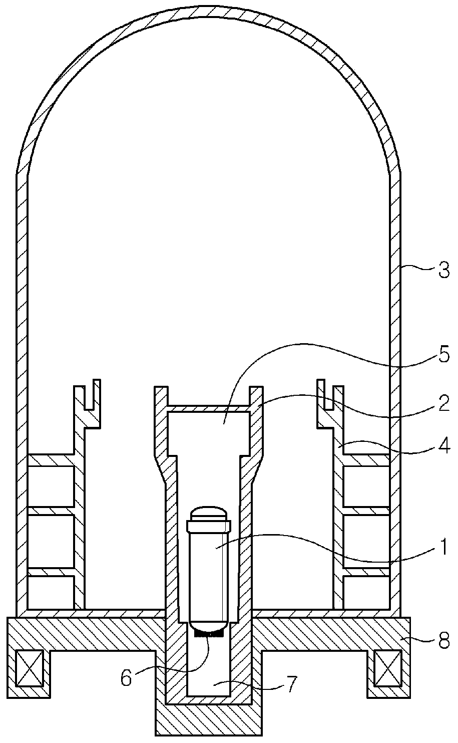
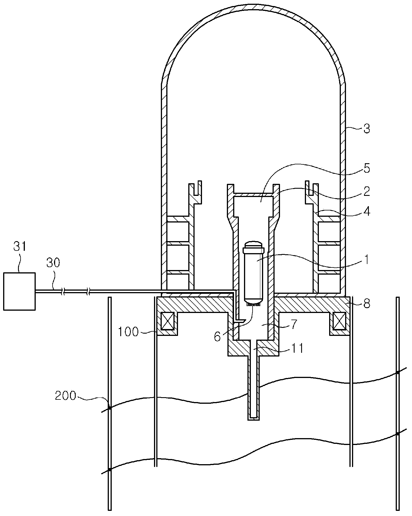
[0024] figure 2 The overall structure of an apparatus for processing molten fuel rods of a nuclear reactor according to an embodiment of the present invention is shown. Such as figure 2 As shown in , in the apparatus of the present invention, an enclosed building 3 is formed around the reactor containment vessel 1 , and the primary barrier 1 and the secondary barrier 4 are installed in the enclosed building 3 . The main barrier 2 is supported by a substrate 8 .

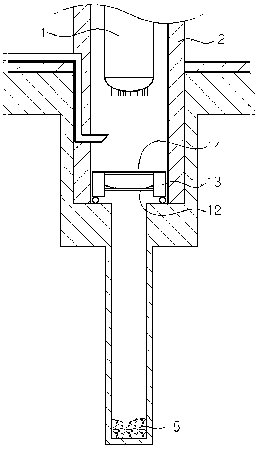
[0025] An opening is formed at the bottom of the main spacer 2 , and a long vertical cavity 11 for embedding molten fuel rods is formed in the base plate 8 supporting the main spacer 2 .

[0026] Because the vertical cavity 11 is formed up to the underground bedrock, the fuel rods 6 fall from the reactor containment vessel 1 ...


PUM


Abstract

The present invention relates to an apparatus for blocking or minimizing radiation leakage by automatically treating molten fuel rods, without power or human effort, when a major accident occurs due to a malfunction of an atomic reactor that leads to melting/damaging of fuel rod containers inside the atomic reactor after the fuel rods, which are used in the atomic reactor, become molten.

Description

technical field [0001] The present invention generally relates to an apparatus for automatically disposing of molten fuel rods when due to natural disasters or abnormal operation of a nuclear reactor (which causes loss of the core cooling function of the nuclear reactor, melting of the fuel rods of the nuclear reactor, damage to the reactor containment vessel, and In the event of a serious accident due to external discharge of molten fuel rods), the device prevents or minimizes radiation leakage without the use of machines or human labor. Background technique [0002] Nuclear power plants are generally divided into nuclear reactor-based nuclear steam supply systems, turbine / generator systems that operate generators through steam supply, and other secondary facilities. Here, a nuclear reactor controls a large amount of energy that is progressively produced when a nuclear reaction occurs, thereby functioning to allow nuclear energy to be converted into electrical energy. [0...

Claims


Application Information

Patent Timeline
IPC IPC(8): G21C9/00G21D3/04
CPCY02E30/40Y02E30/30G21C9/02
Inventor 韩万烨
Owner 昌股能世公司
Why Eureka
Try Eureka