AI technical title is built by Patsnap AI team. It summarizes the technical point description of the patent document.
A tap, intelligent technology, applied in the direction of connections, parts of connecting devices, coupling devices, etc.
Inactive Publication Date: 2014-04-16
NITTO DENKO CORP
View PDF11 Cites 9 Cited by
Summary
Abstract
Description
Claims
Application Information
AI Technical Summary
This helps you quickly interpret patents by identifying the three key elements:
Problems solved by technology
Method used
Benefits of technology
Problems solved by technology
In addition, for the purpose of measuring the power of various home appliances and power supplies, socket-type meters are also commercialized.
Method used
Image
Click on the blue label to locate the original text in one second.
Reading with bidirectional positioning of images and text.
Examples
Embodiment 1
[0330] (Example 1 and Comparative Example)
[0331] As in the comparative example, the triac (TA) was 100 mΩ, the on-resistance was high, and the heat generation of TA itself was high, so the heat generation value was as high as 23.3W. Therefore, the actual measurement temperature is also 200° C. or higher, and it is heated to a temperature that cannot be actually measured and cannot be tolerated in practical use.
[0332] On the other hand, if MOSFET-1 is used instead of TA, the on-resistance is as low as 10.7mΩ, so the calorific value is significantly lower than that of TA, which is 0.6W, and the actual measurement temperature is 65°C, so it can be confirmed that there will be no It will adversely affect the life of the microcomputer control and communication control unit.
[0333] If MOSFET-2 is used, the on-resistance is 38mΩ, which is higher than that of MOSFET-1, so the heat generation value is also higher at 2.1W. As a result, the actual measured temperature exceeds 1...
Embodiment 2
[0337] MOSFET-1 in Example 1 was used. In this Example 2, it was found that the change in the calorific value affects the life of the microcomputer control unit and the like. From the viewpoint of safety, it is desirable that the temperature outside the insertion opening of the power plug is less than 85°C. In addition, in order not to deteriorate the microcomputer control unit, the temperature needs to be lower than 80°C. As for the communication unit, it is desirable that the temperature is lower than 70°C due to the crystal oscillator.
[0338] From the results of Example 2, it can be seen that the heat generated by the MOSFET alone is 1.0 W, but it is necessary to prevent deterioration of the microcomputer control unit and the communication unit.
[0339] [Table 6]
[0340]
Embodiment 3
[0342] Using MOSFET-2 in Example 1, in Figure 6 In the arrangement of the structure shown, MOSFETs were mounted in parallel connection and the heat generation temperature at the time of the socket structure was actually measured.
[0343] A structure in which two MOSFET-2s are connected in parallel is used. Therefore, for example, when 10 A is turned on and there are two MOSFETs-2, a current of 5 A flows through each MOSFET.
[0344] In the actual socket structure shown in Table 7 below, based on the results of actually measuring the heat generation temperature of the MOSFET, it can be seen that if the heat generation value of the MOSFET is 1W or less, the actual measurement temperature is 80°C or less. It was also confirmed that if the heat generation value of the MOSFET is 0.6W or less, the heat generation value can be reduced to 70°C or less, so it can be understood that the heat generation value of the MOSFET should be 0.6W or less in order to prevent heating of the comm...
PUM
Abstract
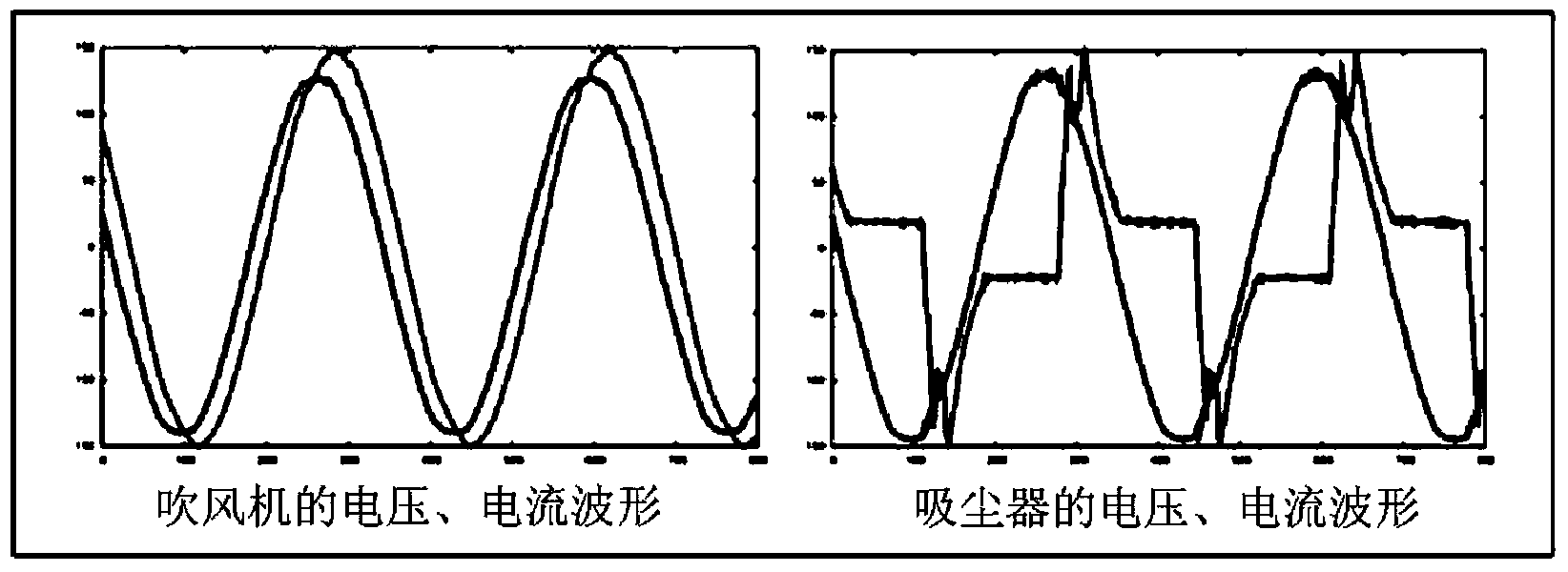
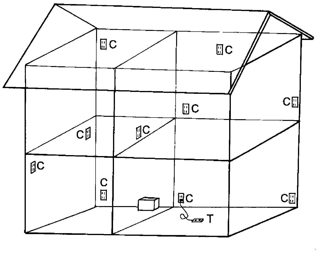
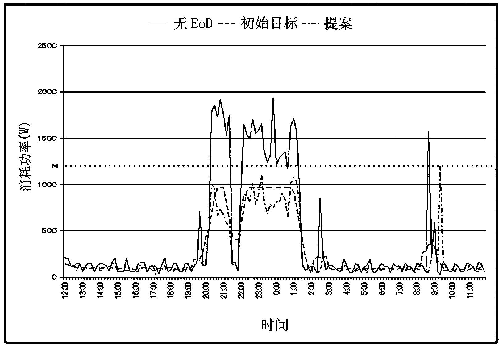
A smart tap into which one or more power plugs can be inserted, the smart tap being characterized by being provided with a voltage waveform measuring means, a current waveform measuring means, a communication means, a control means, and an arithmetic unit, the voltage waveform measuring means and current waveform measuring means being means for measuring a voltage waveform and a current waveform of electricity supplied to each of one or more household electric appliances that are connected via the respective power plugs, the communication means being a means for transmitting the voltage waveform and the current waveform or results of processing the waveforms to a server that is installed at a different location than the smart tap and receiving control signals based on computation results of the server, and the control means being a means for performing on / off control of the electricity supplied to the household electric appliances and regulating the amounts of electricity to be supplied on the basis of the control signals. When powering multiple electric appliances, the smart tap identifies the household electric appliances that are connected with power plugs according to the measurement results of the electricity waveforms of the respective electric devices. Furthermore, the smart tap measures / computes the amounts of electricity required by the household electric appliances, and ascertains the operating status of each electric appliance and detects for abnormal operations to control an EoD system.
Description
technical field [0001] The invention relates to an intelligent tap used for sockets, taps and the like of power plugs of various electrical equipment and household appliances. Background technique [0002] A conventionally known system for visualizing electric power, reducing electric power usage, or supplying electric power to home appliances for managing electric power usage is shown below. [0003] As described in Patent Document 1, there is known a home energy management system that includes: an electric power measurement unit that measures a currently used electric power indicating the electric power currently used by a resident; and an upper limit electric power setting storage unit. , which can set and store the maximum upper limit power amount representing the total power amount that the household can use; the power management unit calculates the current usage in turn according to the input of the above upper limit power amount and the above-mentioned current use pow...
Claims
Application Information
Patent Timeline
Application Date:The date an application was filed.
Publication Date:The date a patent or application was officially published.
First Publication Date:The earliest publication date of a patent with the same application number.
Issue Date:Publication date of the patent grant document.
PCT Entry Date:The Entry date of PCT National Phase.
Estimated Expiry Date:The statutory expiry date of a patent right according to the Patent Law, and it is the longest term of protection that the patent right can achieve without the termination of the patent right due to other reasons(Term extension factor has been taken into account ).
Invalid Date:Actual expiry date is based on effective date or publication date of legal transaction data of invalid patent.

