A high-speed direct-coupled spindle

A technology of direct coupling and main shaft, which is applied in the direction of clamping, supporting, positioning devices, etc., can solve the problems of reducing the service life of bearings, reducing the service life of bearings, affecting the matching accuracy of inner rings and outer rings of bearings, etc., so as to prolong the service life, Improves accuracy and protects against damage

Active Publication Date: 2016-08-17
GUANGZHOU HAOZHI ELECTROMECHANICAL
View PDF6 Cites 0 Cited by
  • Summary
  • Abstract
  • Description
  • Claims
  • Application Information

AI Technical Summary

Problems solved by technology

[0002] The current direct-coupled main shaft usually includes a machine body, a shaft core pivoted inside the machine body through bearings, a pull rod passing through the inside of the shaft core, and an oil cylinder assembly installed on the upper part of the machine body. The piston of the oil cylinder assembly is used to press the tie rod downward. , to complete the unloading process, the cylinder body of the oil cylinder is fixed on the machine body. This rigid connection makes the oil cylinder generate axial thrust on the bearing of the direct-connected main shaft during normal operation, which reduces the service life of the bearing. Specifically, The unloading force of the oil cylinder piston pushing down on the pull rod will be transmitted to the shaft core through the pull rod, so that the shaft core and the machine body will have a downward movement trend in the axial direction. Pushing the bearing will seriously affect the matching accuracy of the inner ring and outer ring of the bearing and reduce the service life of the bearing

Method used


Image

  • A high-speed direct-coupled spindle
  • A high-speed direct-coupled spindle
  • A high-speed direct-coupled spindle

Examples


Embodiment Construction

[0025] Below, in conjunction with accompanying drawing and specific embodiment, the present invention is described further:

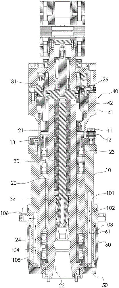
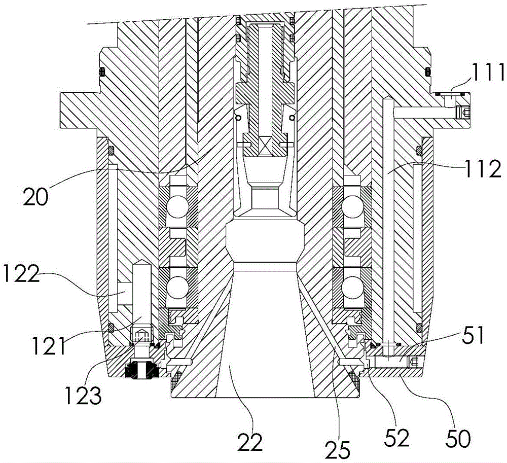
[0026] Such as figure 1 , 2 , 3, it is a high-speed direct-coupled main shaft of the present invention, which includes a body 10, a shaft core 20, a pull rod 30, and an oil cylinder assembly 40, wherein the shaft core 20 is connected inside the body 10, and the shaft core 20 is respectively set by The upper bearing 23 and the lower bearing 24 at the upper and lower ends of the body 10 are pivotally connected inside the body 10, and the bottom end of the shaft core 20 is provided with a tapered hole 22 whose diameter increases from top to bottom, and the pull rod 30 is movable Inside the shaft core 20, the bottom end of the pull rod 30 is connected with a pull claw 32 for fixing the tool. The pull claw 32 cooperates with the above-mentioned tapered hole 22 to realize loading and unloading of the knife. When the pull claw 32 moves upward along the taper...


PUM


Abstract

A high-speed direct connection spindle. The high-speed direct connection spindle comprises: a machine body (10); a spindle core (20), the spindle core (20) being pivotally connected in the machine body (10) through an upper bearing (23) and a lower bearing (24) respectively arranged at the upper end and the lower end of the machine body (10), and a conical hole (22) being provided in the bottom end of the spindle core (20), the diameter of the conical hole (22) being gradually increased from bottom to top; a pull rod (30), the lower end of the pull rod (30) being connected to a pull claw (32) that matches the conical hole (22) and is used for fixing a cutter, and the upper end of the pull rod (30) having a cutter hitting disk (31) fixed thereto; a reset spring (21), mounted between the spindle core (20) and the pull rod (30); and an oil cylinder assembly (40), comprising a cylinder body (41) positioned above the top end of the machine body and a piston (42) mounted inside the cylinder body and used for pushing against the cutter hitting disk (31) downwards. The cylinder body (41) is movably provided with a plurality of connecting pieces penetrating therethrough, the part, penetrating through the lower end of the cylinder body (41), of each connecting piece is fixedly connected to the machine body (10), and each connecting piece has an elastic element sleeved thereon. The cylinder body (41) of the oil cylinder is mounted on the machine body (10) in a floating manner, and the axial thrust applied by the oil cylinder to the spindle core (20) when the cutter is assembled or disassembled can be counteracted, so that the bearings are protected from being damaged, and the service life of the bearings is prolonged.

Description

technical field [0001] The invention relates to a high-speed direct-coupled spindle. Background technique [0002] The current direct-coupled main shaft usually includes a machine body, a shaft core pivoted inside the machine body through bearings, a pull rod passing through the inside of the shaft core, and an oil cylinder assembly installed on the upper part of the machine body. The piston of the oil cylinder assembly is used to press the tie rod downward. , to complete the unloading process, the cylinder body of the oil cylinder is fixed on the machine body. This rigid connection makes the oil cylinder generate axial thrust on the bearing of the direct-connected main shaft during normal operation, which reduces the service life of the bearing. Specifically, The unloading force of the oil cylinder piston pushing down on the pull rod will be transmitted to the shaft core through the pull rod, so that the shaft core and the machine body will have a downward movement trend in...

Claims


Application Information

Patent Timeline
Patent Type & Authority Patents(China)
IPC IPC(8): B23Q3/155B23B19/02
CPCB23Q1/70B23B31/265B23B2231/50B23B2260/136
Inventor 汤秀清
Owner GUANGZHOU HAOZHI ELECTROMECHANICAL
Why Eureka
Try Eureka