Automatic clamping and fetching device

A power and power shaft technology, applied in the field of automatic gripping devices, can solve the problems of unreliable grasping of materials by a manipulator, complicated production and processing, long design cycle, etc., and achieves wide practicability and promotion value, low cost and good maneuverability. Effect

Active Publication Date: 2014-04-23
昆山德系智能装备有限公司
View PDF7 Cites 11 Cited by
  • Summary
  • Abstract
  • Description
  • Claims
  • Application Information

AI Technical Summary

Problems solved by technology

[0002] In the process of industrial automation production, manipulators are needed in many places. Most of the solutions are realized by using cylinders supplemented by corresponding fixtures. The structure is more complicated, the design cycle is longer, the production and processing are complicated, and the installation is cumbersome. , low accuracy, low efficiency, and the manipulator is not reliable in grabbing materials

Method used


Image

  • Automatic clamping and fetching device
  • Automatic clamping and fetching device
  • Automatic clamping and fetching device

Examples


Embodiment Construction

[0016] The present invention will be further described below in conjunction with the accompanying drawings.

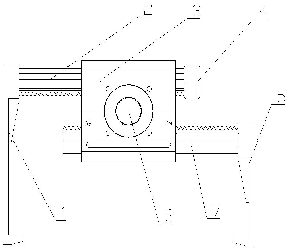
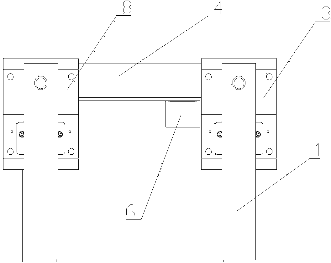
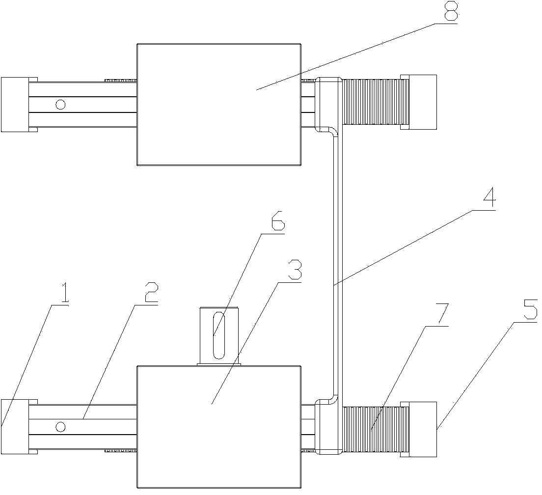
[0017] The present invention includes a power automation module 3, a driven automation module 8 and a connecting plate 4. The power automation module 3 includes a power shaft 6, a housing, a guide rail rack I2 and a guide rail rack II7, and two vertically opposite sides of the housing A mounting hole for the power shaft 6 is provided, bearings are arranged at both ends of the power shaft 6, and the bearings are installed on the power shaft mounting hole, one end of the power shaft 6 is arranged on the outside of the housing, and a There are gears, the guide rail rack I2 and the guide rail rack II7 vertically pass through the two vertical sides of the housing parallel to the power shaft 6, the tooth surfaces of the guide rail rack I2 and the guide rail rack II7 are opposite, and mesh with the gears respectively, and The forward direction of the two rail racks is opposit...


PUM


Abstract

The invention discloses an automatic clamping and fetching device. A power automation module comprises a power shaft, a shell, a guide rail rack I and a guide rail rack II, wherein a power shaft mounting hole is formed at each of two vertically opposite lateral surfaces of the shell; a bearing is mounted at each of two ends of the power shaft and is mounted on the power shaft mounting hole; one end of the power shaft is mounted at the outer side of the shell; the power shaft in the shell is provided with a gear; the guide rail rack I and the guide rail rack II vertically pass through two vertical lateral surfaces of the shell which are parallel to the power shaft; the tooth surfaces of the guide rail racks are opposite to each other, move forwardly in different directions and are respectively engaged with the gear in fit manner; a mechanical gripper I is firmly connected with one end of the guide rail rack I; the end of the guide rail rack II symmetrical to the guide rail rack I is provided with a mechanical gripper II; the other end of the guide rail rack I is firmly connected with a connecting plate; the other end of the connecting plate is firmly connected with a driven automation module; the power automation module and the driven automation module are parallel to each other. The automatic clamping and fetching device is simple in structure and is easy to achieve.

Description

technical field [0001] The invention relates to a manipulator for material clamping, in particular to an automatic clamping device. Background technique [0002] In the process of industrial automation production, manipulators are needed in many places. Most of the solutions are realized by using cylinders supplemented by corresponding fixtures. The structure is more complicated, the design cycle is longer, the production and processing are complicated, and the installation is cumbersome. , low accuracy, low efficiency, and the manipulator is not reliable in grabbing materials. Contents of the invention [0003] The object of the present invention is to provide an automatic clamping device with simple structure, convenient operation, high accuracy and high efficiency. [0004] In order to achieve the above-mentioned purpose, the technical solution adopted in the present invention is: the automatic clamping device includes a power automation module, a driven automation mod...

Claims


Application Information

Patent Timeline
IPC IPC(8): B25J15/08
Inventor 周翔
Owner 昆山德系智能装备有限公司
Why Eureka
Try Eureka