
Electric vehicle and driving system thereof

A technology for electric vehicles and drive systems, applied in electric vehicles, control drives, vehicle components, etc., can solve the problems of difficult waterproof protection, inconvenient maintenance, and high condition requirements at the bearing holes.

Active Publication Date: 2014-04-23
BAIC MOTOR CORP LTD
View PDF4 Cites 15 Cited by
  • Summary
  • Abstract
  • Description
  • Claims
  • Application Information

AI Technical Summary

Problems solved by technology

[0004] The existing technology has the following problems: For vehicles with high power requirements, vehicles driven independently by dual motors have higher requirements on the conditions of the motors on both sides, which greatly increases the production cost
4. The hub motor of the hub motor drives the car. The hub motor has disadvantages: the hub motor itself is heavy, the fault is high, and the maintenance is inconvenient. The hub must be disassembled before maintenance. The electronic components in the motor are easily damaged. , especially the waterproof protection at the bearing hole is more difficult, and the cost of the hub motor is higher, etc.

Method used


Image

  • Electric vehicle and driving system thereof
  • Electric vehicle and driving system thereof

Examples


Embodiment Construction

[0022] In order to make the technical problems, technical solutions and advantages to be solved by the present invention clearer, the following will describe in detail with reference to the drawings and specific embodiments.

[0023] In the embodiment of the present invention, a rear-wheel coupling drive system that can reduce the power of one side motor and maximize the use of motor energy is provided.

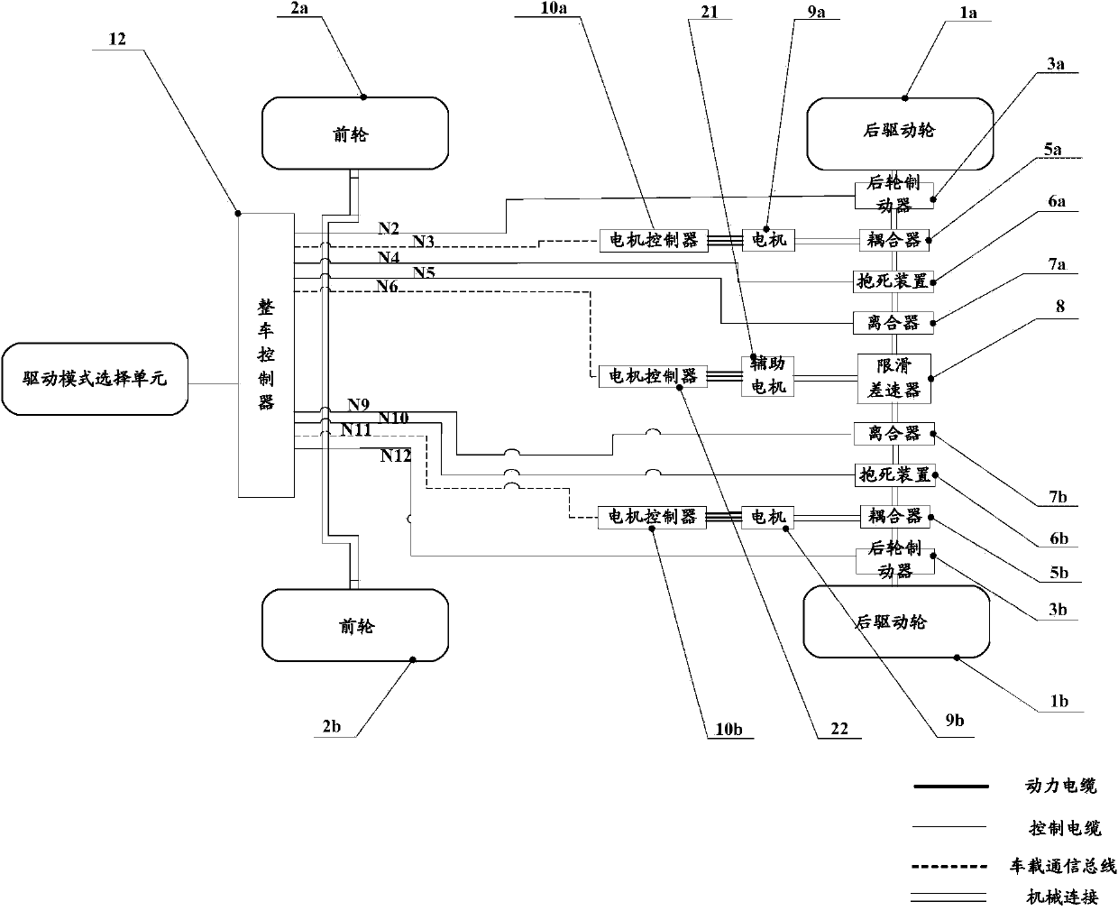
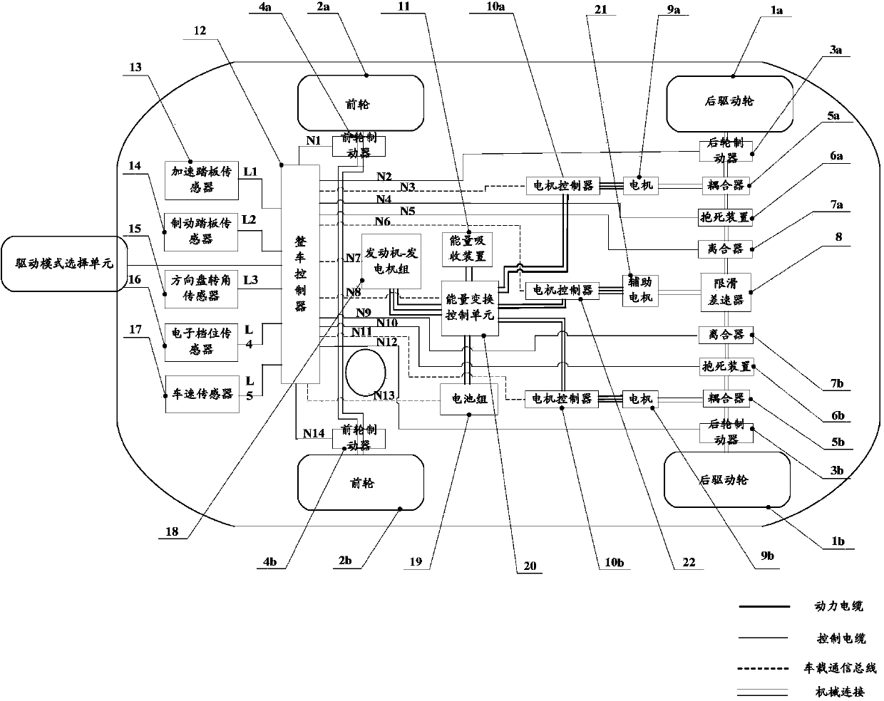
[0024] An embodiment of the present invention provides an electric vehicle drive system, such as figure 1 As shown, including: mechanical system and electrical system, the electrical system includes power system and control system;

[0025] The drive mode selection unit is used to switch between the dual-motor independent drive mode and the auxiliary motor coupled drive mode, including:

[0026] When the rear drive wheels 1a and the rear drive wheels 1b on both sides require power less than or equal to the maximum power of the motor 9a and motor 9b on one side, the dual-moto...


PUM


Abstract

An embodiment of the invention provides an electric vehicle and a driving system thereof, and is applied to the field of electric vehicles. The electric vehicle comprises a mechanical system, an electric system and a driving mode selection unit. The driving mode selection unit is used for switching between a dual-motor independent-drive travelling mode and an auxiliary-motor coupling-drive travelling mode. The driving mode selection unit comprises the dual-motor independent-drive travelling mode, the auxiliary-motor coupling-drive travelling mode and a vehicle control unit. The dual-motor independent-drive travelling mode is adopted when the travelling power of rear drive wheels on two sides is smaller than or equal to the highest power of motors on one side, and the auxiliary-motor coupling-drive travelling mode is adopted when the travelling power of the rear drive wheels on two sides is larger than the highest power of the motors on one side. The vehicle control unit is used for controlling corresponding different electromagnetic clutches and electromagnetic-clutch frictional-disk locking devices in the dual-motor independent-drive travelling mode and in the auxiliary-motor coupling-drive travelling mode respectively.

Description

technical field [0001] The invention relates to electric vehicle technology, in particular to an electric vehicle and its driving system. Background technique [0002] For an engine-driven car, the drive system relies on the power provided by the engine, and the power is transmitted to the wheels through the transmission, differential and half shafts. At present, most cars are driven by the front wheels, and the front wheels have a set of mechanical manipulation structures to make the front wheels produce a certain angle of rotation to achieve steering. However, such a system is due to the steering and driving of the front wheels, so the structure of the entire mechanical system is very complicated. At the same time, in today's increasingly severe energy environment, the range of use of traditional engines will be more and more limited, and people are looking for a cleaner, more environmentally friendly new energy source, so electric vehicles are getting more and more attent...

Claims


Application Information

Patent Timeline
IPC IPC(8): B60L15/32
Inventor 柳龙陈德利
Owner BAIC MOTOR CORP LTD
Learn More