
Trigger device

A technology of trigger device and light source transmitter, which is applied in the direction of conveyor control device, transportation and packaging, conveyor objects, etc., and can solve the problems that photoelectric switches cannot accurately detect medicine ingots, limited settings, and photoelectric switch misjudgments, etc.

Inactive Publication Date: 2014-04-23
吴俊娟
View PDF4 Cites 1 Cited by
  • Summary
  • Abstract
  • Description
  • Claims
  • Application Information

AI Technical Summary

Problems solved by technology

[0002] Generally, the surface of the tablet is in the shape of a raised central arc, and the tablet is transported to a processing machine (such as a laser drilling machine) by a conveyor belt for processing during the post-production process. In order to ensure that the processing machine can accurately To process pills, a photoelectric switch is often installed on the conveyor belt, and the pills are used to generate a trigger signal through the trigger device, so that the processing machine can process the pills accurately. However, when the pills are on the conveyor belt, in order to speed up the production process , There is often only a very small gap between two pills or even adjacent to each other, often causing misjudgment by the photoelectric switch, and the setting of the photoelectric switch is limited by the conveyor belt, so that the photoelectric switch cannot accurately detect the pills

Method used


Image

  • Trigger device

Examples


Embodiment Construction

[0008] The present invention will be described in further detail below in conjunction with the accompanying drawings.

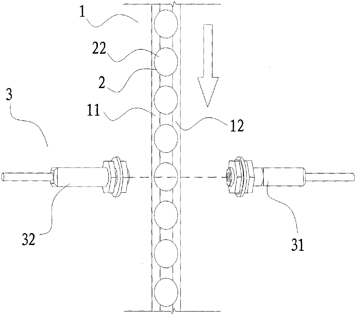
[0009] Such as figure 1 As shown, a trigger device includes a conveyor belt group 1 and a photoelectric switch 3, and the conveyor belt group 1 is transported with pills 2, and the pills 2 are arranged at intervals on the conveyor belt group 1, wherein the conveyor belt group 1 is It has the 1st conveyor belt 11 and the 2nd conveyor belt 12 arranged side by side. The tablet 2 has a base 21, the outer edge of the base 21 is in the shape of a closed arc, the upper and lower sides of the base 21 are respectively formed with an upper surface 22 and a lower surface 23, and the upper surface 22 of the base 21 is in the shape of a convex arc in the center. The lower surface 23 is in the shape of a convex arc at the center, and the two sides of the lower surface 23 respectively bear against the first conveyor belt 11 and the second conveyor belt 12 .

[0010] The p...


PUM


Abstract

The invention discloses a trigger device which comprises a conveying belt group and photoelectric switches. Ingot-shaped tablets are conveyed on the conveying belt group and provided with bases, the peripheries of the bases are closed arcs, an upper surface and a lower surface are formed on the upper side and the lower side of each base respectively, the upper surfaces of the bases are central projecting convex arcs, the lower surfaces of the bases are abutted to the conveying belt group, a light source transmitter and a light source receiver are arranged on the photoelectric switches and on two sides of the conveying belt group respectively, acute angles are formed among the light source transmitter, the light source receiver and the bases of the ingot-shaped tablets, so that the ingot-shaped tablets pass gaps of the light source transmitter and the light source receiver, joints of the bases and sides of the upper surfaces of the ingot-shaped tablets shield the light source transmitter to trigger the photoelectric switches, so that the photoelectric switches can be triggered when the joints of the bases and the sides of the upper surfaces of the ingot-shaped tablets pass the photoelectric switches by the aid of the acute angles formed by the trigger device and the ingot-shaped tablets, and the photoelectric switches accurately detect the ingot-shaped tablets and generate trigger signals.

Description

technical field [0001] The invention relates to a trigger device, in particular to a trigger device which utilizes a spindle transported on a conveyer belt to cover a photoelectric switch so that the photoelectric switch generates a trigger signal. Background technique [0002] Generally, the surface of the tablet is in the shape of a raised central arc, and the tablet is transported to a processing machine (such as a laser drilling machine) by a conveyor belt for processing during the post-production process. In order to ensure that the processing machine can accurately To process pills, a photoelectric switch is often installed on the conveyor belt, and the pills are used to generate a trigger signal through the trigger device, so that the processing machine can process the pills accurately. However, when the pills are on the conveyor belt, in order to speed up the production process , There is often only a very small gap or even adjacent to each other between the two pill...

Claims


Application Information

Patent Timeline
Patent Type & Authority Applications(China)
IPC IPC(8): B65G43/08
Inventor 吴俊娟
Owner 吴俊娟
Learn More