Dust collection disc of cleaning trolley

A vacuum cleaner and cleaning vehicle technology, which is applied to road cleaning, cleaning methods, construction, etc., can solve the problems of complex structure of vacuum cleaner, high maintenance cost, unsatisfactory cleaning effect, etc., to improve the working ability and service life, Reduced maintenance costs and good floor cleaning effects

Inactive Publication Date: 2014-04-23
BEIJIG TIANLUTONG TECH
View PDF8 Cites 19 Cited by
  • Summary
  • Abstract
  • Description
  • Claims
  • Application Information

AI Technical Summary

Problems solved by technology

[0003] The purpose of the present invention is to solve the technical problems of the previous patented cleaning vehicle’s dust-absorbing disc with relatively complex structure, unsatisfactory cleaning effect and high maintenance cost, and to provide a technical improvement with simple structure, good cleaning effect and low maintenance cost new plan

Method used


Image

  • Dust collection disc of cleaning trolley
  • Dust collection disc of cleaning trolley
  • Dust collection disc of cleaning trolley

Examples


Embodiment 1

[0024] Attached below figure 1 , attached figure 2 , attached image 3 And attached Figure 4 The structure of the dust suction pan of the present invention will be described in detail.

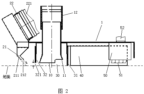
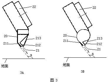
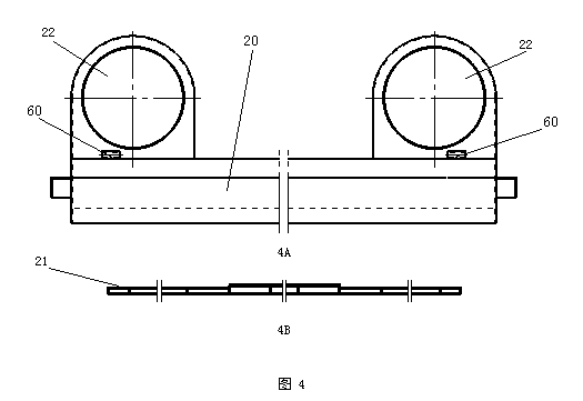
[0025] figure 1 Shown is a schematic plan view of an embodiment of the dust suction pan 1 of the present invention, figure 2 It is a schematic cross-sectional view along the LL' direction of the suction cup 1. Such as figure 1 , figure 2 As shown in , the dust suction plate 1 includes a dust suction port 10 and a strip-shaped air channel 20 arranged on the plate body. The tuyere 22 is connected to the fan return duct 221 , and a slit-type air duct outlet 21 is arranged on the lower side of the strip-shaped air duct 20 along the air duct. The direction of the air outlet 21 corresponds to the dust suction port 10. When the fan is working, the high-speed air flow enters the strip air passage 20 from the fan return pipe 221 through the air inlet 22, and then sprays from the air outlet ...

Embodiment 2

[0031] In this embodiment, the structural design of the suction cup 1 is the same as the content of the first embodiment, and will not be repeated here. figure 1 , attached figure 2 The specific content of this embodiment will be described in detail.

[0032] in the attached figure 1 , attached figure 2 The structure of a specific embodiment of the dust suction pan is shown in , and the structure of the dust suction pan 1 of this embodiment is described in detail with reference to the L direction, ie, the driving direction, as the front direction. A front deflector rubber plate 31 is provided in front of the dust suction port 10, a rear deflector rubber plate 32 is provided behind the dust suction port 10, and the front deflector rubber plate 31 is connected with the rear deflector. The rubber plate 32 encloses the area around the dust suction port 10 to form a negative pressure area 30 of the dust suction port, which is equivalent to forming a large dust suction port; a ...

Embodiment 3

[0035] In this embodiment, the same parts about the structure design of the dust-absorbing pan as those of the previous embodiments will not be repeated here, and only the different parts will be combined with the attached parts below. figure 1 , attached figure 2 , attached Figure 4 The specific content of this embodiment will be described in detail.

[0036] In this embodiment, the structure of the dust suction pan 1 of this embodiment is described in detail with the L direction as the driving direction as the forward direction. The dust suction pan 1 is provided with two suction ports 10, which are symmetrically located on both sides under the main beam of the vehicle body chassis (not shown in the figure); the front deflector rubber plate 31 and the rear deflector rubber plate 32 correspond to the two The dust suction port 10 is bent so that it is bent to form two independent vacuum port negative pressure areas 30; the scraper 40 is arranged in an inverted V shape in f...


PUM


Abstract

The invention discloses a dust collection disc of a cleaning trolley. The dust collection disc comprises a suction inlet and a strip air duct which are formed on the disc body; the suction inlet is connected with a suction pipe; the air duct is connected with an air outlet pipe of a fan; a slit type air duct air outlet is formed in the lower side of the stripe air duct along the air duct; the orientation of the air duct air outlet corresponds to that of the suction inlet; high-speed air draft blown out from the air duct air outlet blows garbage on the ground to the suction inlet. The dust collection disc has a simple structure, is skillful in design, properly solves the problems of high energy consumption, unsatisfactory cleaning effect, high maintenance cost and the like in the conventional dust collection disc, has a simple structure, is low in maintenance cost, saves energy consumption, and is high in cleaning efficiency, and compared with the prior art, the dust collection disc has very positive technical effect.

Description

technical field [0001] The invention relates to a dust suction device for a cleaning vehicle, in particular to a dust suction plate for a cleaning vehicle. Background technique [0002] The structure of the dust collection device of the existing cleaning vehicle is relatively complicated, the energy consumption is high, the cleaning effect is not satisfactory, and there are also problems such as high maintenance cost. In the applicant's patent No. 200910180280.8, the invention name is multi-function cleaning vehicle. The air circulation spray suction design of the airflow has a relatively complicated structure. Because the angles of each rubber nozzle relative to the air suction port are different, the airflow blown out interferes with each other and cancels each other out. When the speed is fast, there will be garbage left on the ground, and the cleaning effect will be affected. Moreover, because the vacuum pan has a double-layer plate structure, after a long period of use...

Claims


Application Information

Patent Timeline
Patent Type & Authority Applications(China)
IPC IPC(8): E01H1/08
Inventor 杜强国
Owner BEIJIG TIANLUTONG TECH
Why Eureka
Try Eureka