Coupled vibration simulation experiment table of aero-engine hydraulic pipeline system

A technology for aero-engine and hydraulic pipelines, which is applied in the testing of fluid pressure actuation systems, mechanical equipment, fluid pressure actuation devices, etc. Fully reflect the vibration of aero-engine hydraulic piping system and other issues

Active Publication Date: 2014-04-23
NORTHEASTERN UNIV
View PDF3 Cites 13 Cited by
  • Summary
  • Abstract
  • Description
  • Claims
  • Application Information

AI Technical Summary

Problems solved by technology

[0003] At present, most of the vibration tests of hydraulic piping systems at home and abroad use single pipes as the research and test objects, but it is difficult for aeroengine hydraulic piping systems to study the vibration characteristics of the entire piping system based on the test data of a single pipe, that is, the piping Coupled vibration characteristics with the pipeline
Therefore, relevant technical perso

Method used


Image

  • Coupled vibration simulation experiment table of aero-engine hydraulic pipeline system
  • Coupled vibration simulation experiment table of aero-engine hydraulic pipeline system
  • Coupled vibration simulation experiment table of aero-engine hydraulic pipeline system

Examples


Embodiment Construction

[0021] The present invention will be further described in detail below in conjunction with the accompanying drawings and specific embodiments.

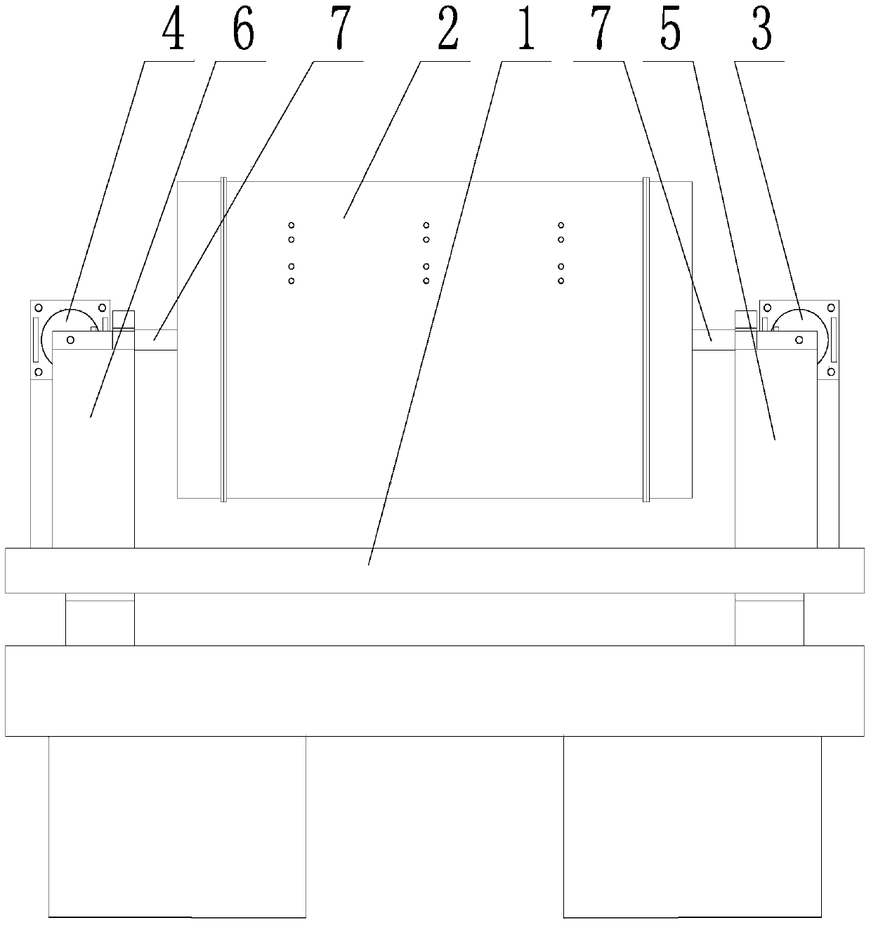
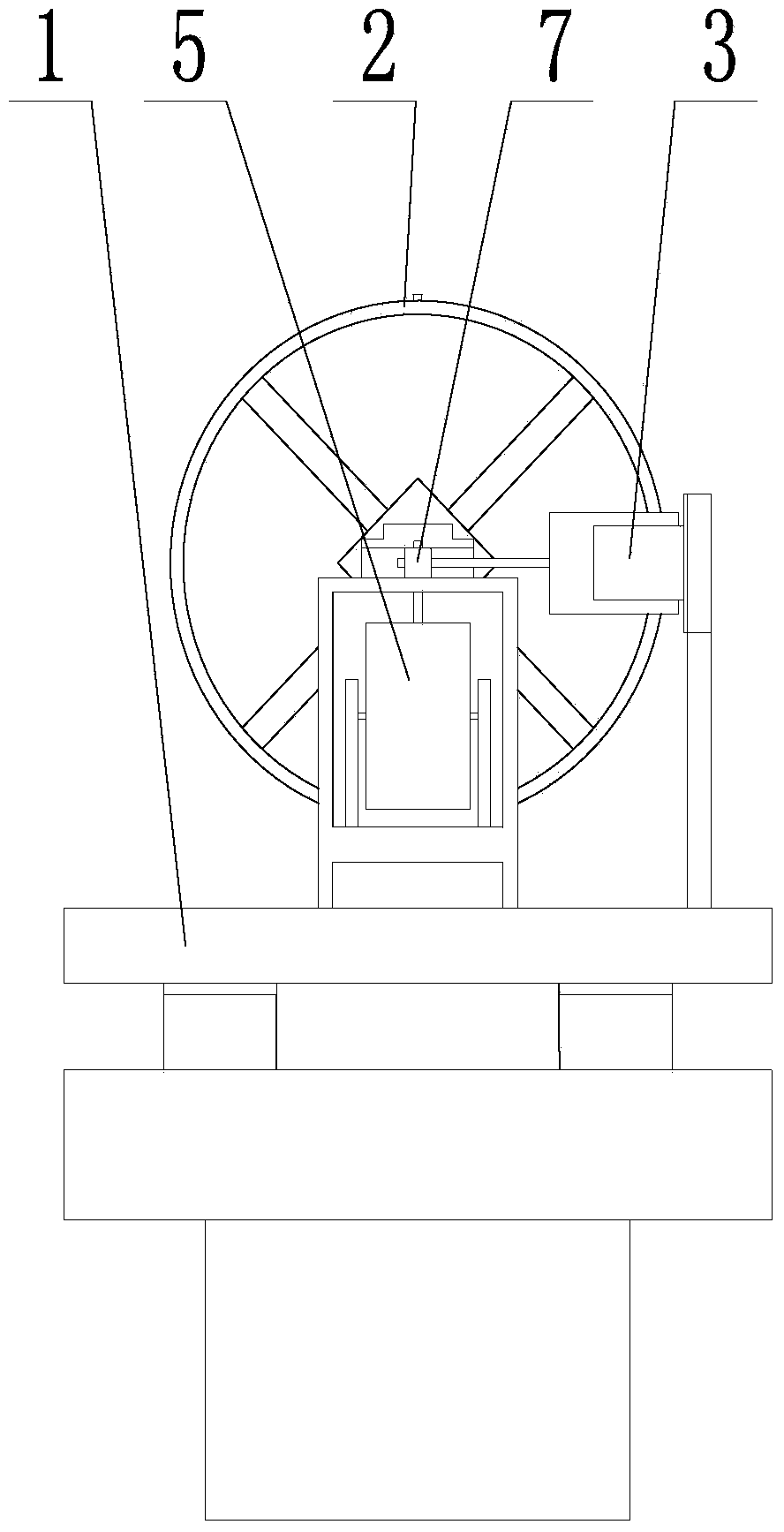
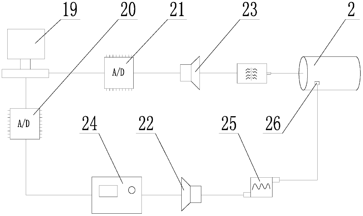
[0022] Such as figure 1 , 2 , Shown in 3 and 4, an aero-engine hydraulic pipeline system coupled vibration simulation test bench, including a pipeline carrier vibration unit, a signal acquisition analysis control unit and a hydraulic pipeline oil supply system unit;

[0023] The pipeline carrier vibration unit includes a base 1, a casing body 2 and an exciter. The casing body 2 adopts a cylindrical structure to simulate an aircraft engine casing, and the casing body 2 is located on the base 1. , several clamps are arranged on the outer cylinder wall of the casing body 2, and the hydraulic pipeline for testing can be fixed on the outer cylinder wall of the casing body 2 through the clamps; a vibration exciter is installed on the base 1, The vibration output end of the vibrator is connected with the casing body 2 through the guide rod...


PUM


Abstract

The invention provides a coupled vibration simulation experiment table of an aero-engine hydraulic pipeline system and belongs to the technical field of pipe vibration simulation experiments. The coupled vibration simulation experiment table comprises a pipeline carrier shock excitation unit, a signal collection analysis control unit and a hydraulic pipeline oil supply system unit. Compared with the prior art, a testing hydraulic pipeline of the hydraulic pipeline oil supply system unit is installed on a case body of the pipeline carrier shock excitation unit. Due to the fact that the case body simulates a structure of an aero-engine case, the vibration influence of the aero-engine case to the testing hydraulic pipe can be simulated, simulation of different installing modes of an aero-engine hydraulic pipeline is achieved by changing the installing-clamping position of a hoop on the case body, a vibration signal acquired by a displacement sensor of the signal collection analysis control unit is analyzed and processed to obtain vibration characteristics and a mechanism, a reasonable basis is provided for hydraulic pipeline system vibration faults, and the vibration situation of the hydraulic pipeline system can be really reflected.

Description

technical field [0001] The invention belongs to the technical field of pipeline vibration simulation experiments, in particular to an aeroengine hydraulic pipeline system coupling vibration simulation test bench. Background technique [0002] The stability of the hydraulic piping system of an aero-engine directly affects the safe operation of the aero-engine, and the vibration test of the hydraulic piping system is an effective means to improve the stability of the aero-engine. Vibration testing can analyze the characteristics and mechanism of vibration, and provide Provide a reasonable basis for the vibration failure of the hydraulic pipeline system. [0003] At present, most of the vibration tests of hydraulic piping systems at home and abroad use single pipes as the research and test objects, but it is difficult for aeroengine hydraulic piping systems to study the vibration characteristics of the entire piping system based on the test data of a single pipe, that is, the p...

Claims


Application Information

Patent Timeline
IPC IPC(8): F15B19/00
Inventor 周恩涛韩清凯林君哲范晓宇吕振
Owner NORTHEASTERN UNIV
Why Eureka
Try Eureka