
Device and method for automatic circulation material distribution control of furnace top ore bin of vertical furnace ore returning furnace

A technology of automatic circulation and material distribution, applied in furnaces, vertical furnaces, furnace types, etc., can solve problems such as large area, frequent operations by operators, and high price

Active Publication Date: 2014-04-23
NORTHEASTERN UNIV
View PDF7 Cites 8 Cited by
  • Summary
  • Abstract
  • Description
  • Claims
  • Application Information

AI Technical Summary

Problems solved by technology

However, due to the large area of ​​the feeding bin on the furnace top, it is difficult to meet the requirements of the entire bin with single-point distribution, and it is often necessary to select multiple distribution points for circular distribution.
If level gauges are installed at these distributing points, it is not only expensive, but also difficult to choose a suitable fixed position to install the level gauge to detect the material level in real time
Since there is no reliable and practical automatic material distribution control system, the operator mainly relies on the operator to manually operate the trolley, move the trolley to the fabric position according to the on-site warehouse position, and need to observe the material level of other positions in real time
There are major problems in the above operation mode: due to the continuous operation of the material distribution process, the operator operates frequently and the work intensity is high; the site is dusty, noisy, and the working environment is extremely harsh; when the material flow changes or the operator does not operate in time, resulting Uneven level, even dangerous working conditions, such as low material level at the top of the shaft furnace, resulting in gas leakage, which poses a major threat to the safety of production personnel

Method used

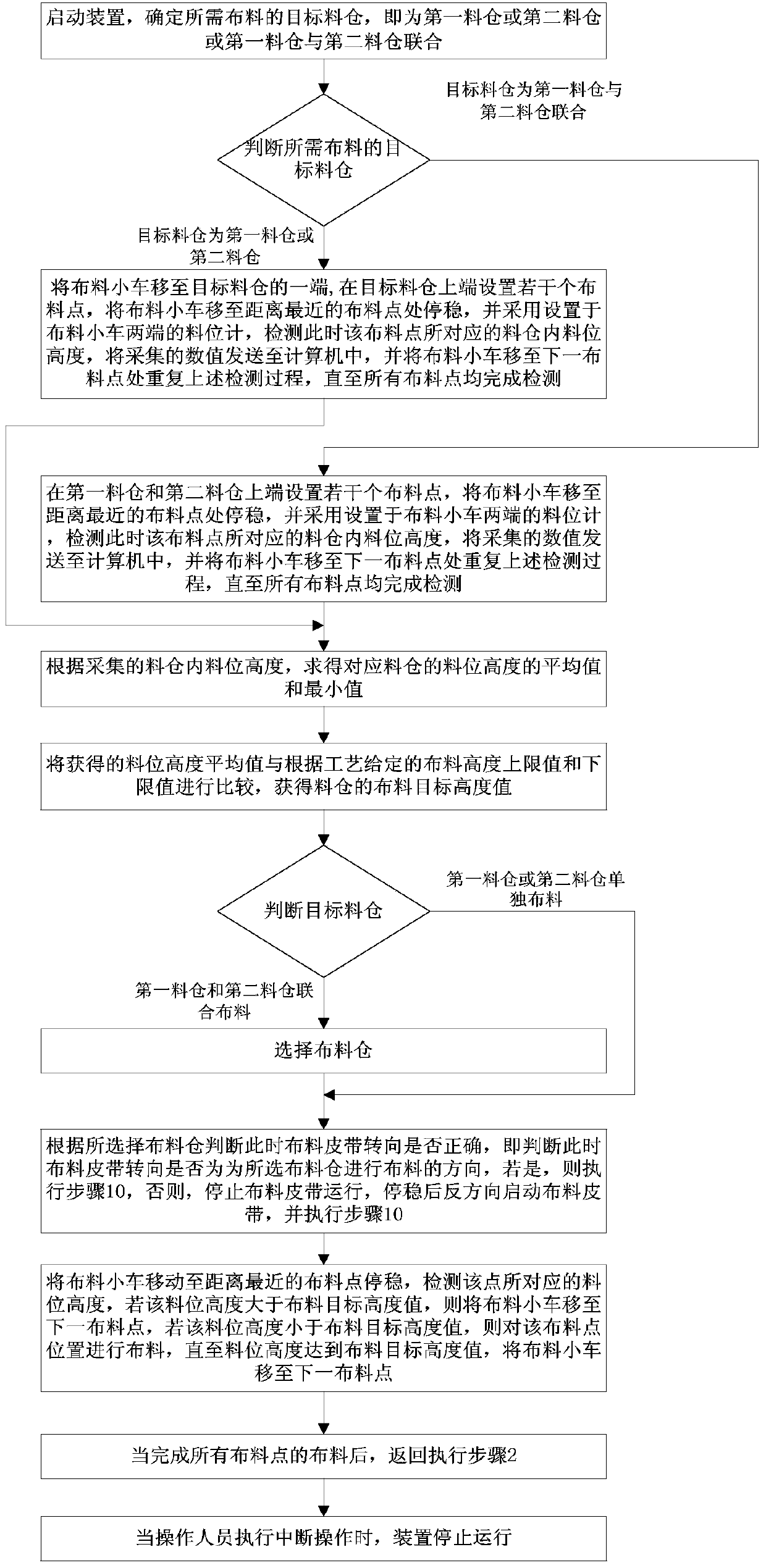
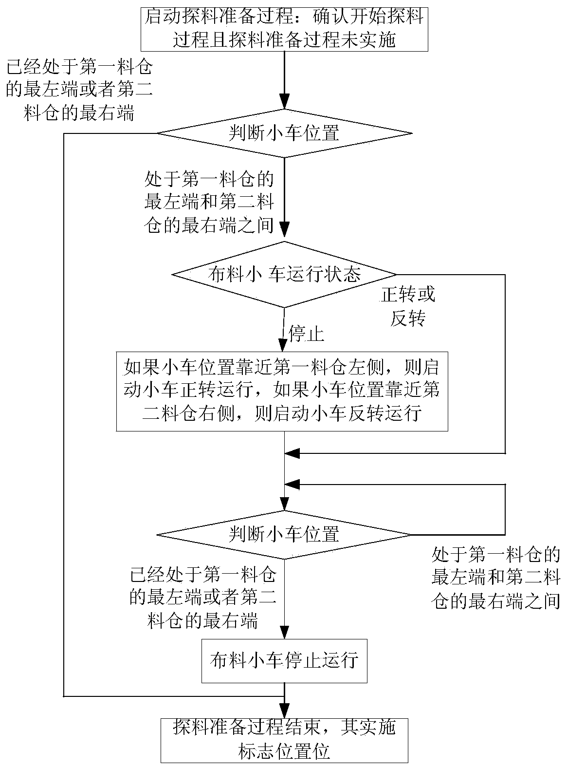

Image

  • Device and method for automatic circulation material distribution control of furnace top ore bin of vertical furnace ore returning furnace
  • Device and method for automatic circulation material distribution control of furnace top ore bin of vertical furnace ore returning furnace
  • Device and method for automatic circulation material distribution control of furnace top ore bin of vertical furnace ore returning furnace

Examples


Embodiment Construction

[0048] An embodiment of the present invention will be further described below in conjunction with the accompanying drawings.

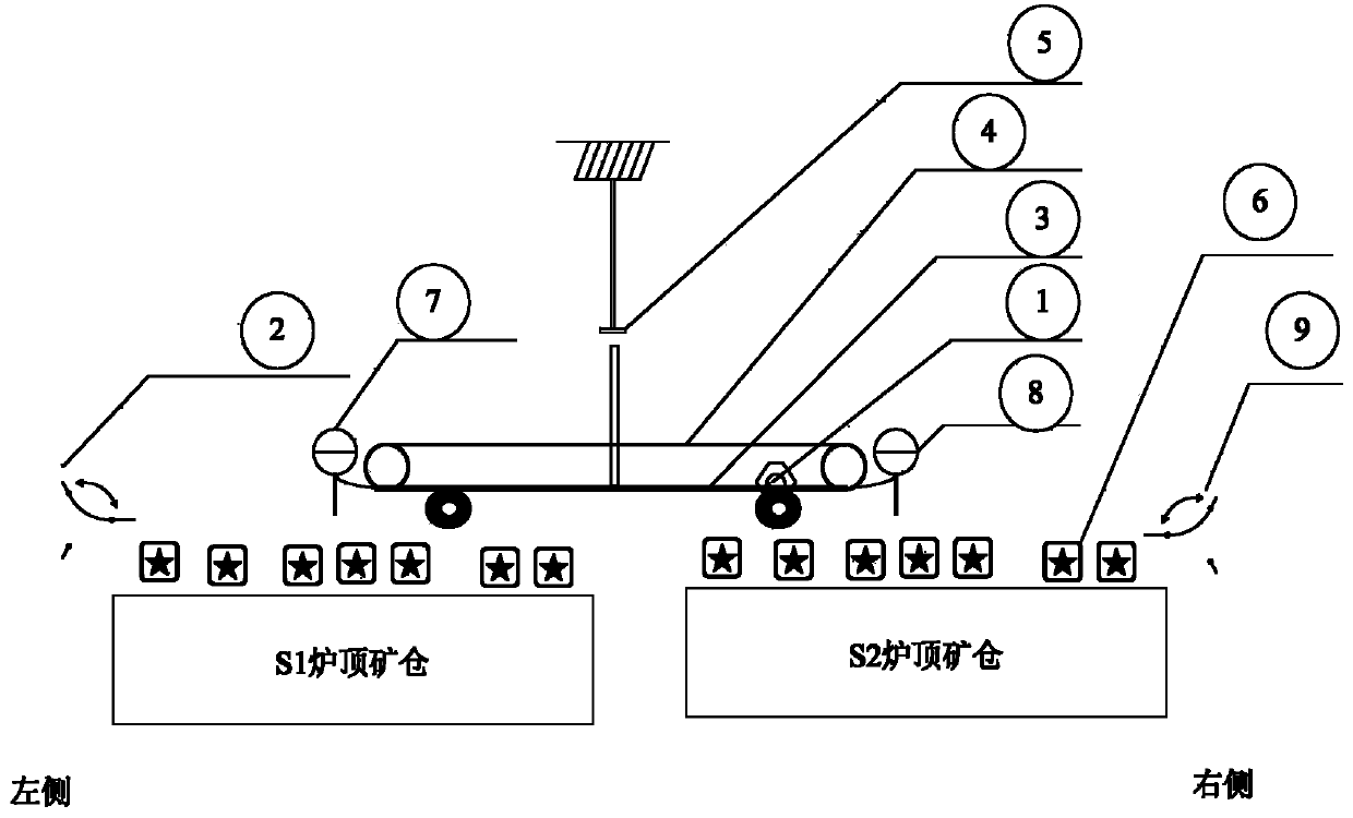
[0049] like figure 1 As shown, in the embodiment of the present invention, taking the process flow of using the reversible material distribution belt 4 and the material distribution trolley 3 as the material for the return ore bin S1 and the return ore bin S2 as an example, the upstream feeding belt is a reversible distribution belt. Material, the reversible warehouse belt conveyor trolley forward turns to S1 mine cloth, the reversible warehouse belt conveyor trolley reverses to S2 mine fabric, the reversible warehouse belt conveyor is fixed on the reversible warehouse belt conveyor On the belt conveyor trolley, it moves with the fabric trolley. The material distributing system composed of the feeding belt, the distributing belt and the distributing trolley, its device part includes: the first material level gauge 7, the second material level gauge 8,...


PUM


Abstract

The invention relates to a device and method for automatic circulation material distribution control of a furnace top ore bin of a vertical furnace ore returning furnace and belongs to the field of automatic process control. The device and method for automatic circulation material distribution control aims to solve the problem that in the vertical furnace ore returning furnace material distributing process, manual operation is frequency, working intensity is high, the site environment is poor, and risks are high; by automatic material distributing control, uniform continuous safe material distribution of the ore furnace top ore bin is achieved, the material distribution process can automatically run for a long term through the method, a system is good in reliability and has material distribution evenness, the influence on health caused by the fact that material distribution operators work in the poor environment for a long term is avoided, labor intensity is greatly reduced, and the device and method for automatic circulation material distribution control are of great significance for guaranteeing that a vertical furnace runs safely stably efficiently.

Description

technical field [0001] The invention belongs to the field of automatic process control, and in particular relates to an automatic circulation control device and method for the top ore bunker of a shaft furnace returning ore furnace. Background technique [0002] For the roasting production process of the shaft furnace ore-returning furnace, the ore required comes from the tailings obtained from raw ore roasting and dry separation. In order to ensure that the silo meets a certain material level requirement in real time, it is necessary to realize circular distribution according to the material level distribution. However, due to the large area of ​​the feeding bin on the top of the furnace, it is difficult to meet the requirements of the entire bin with single-point distribution, and it is often necessary to select multiple distribution points to circulate the distribution. If level gauges are installed at these distributing points, it is not only expensive, but also difficul...

Claims


Application Information

Patent Timeline
IPC IPC(8): F27B1/20F27B1/26
Inventor 张立岩岳恒李健郑秀萍柴天佑
Owner NORTHEASTERN UNIV
Learn More