Natural gas conveying pipe system pressure test device

A technology for pressure testing and conveying pipes, which is applied in the direction of measuring devices, testing of machines/structural components, instruments, etc., can solve problems such as difficult testing, and achieve the effects of shortening the testing cycle, high testing safety, and saving costs

Active Publication Date: 2014-04-23
南通中集太平洋海洋工程有限公司
View PDF4 Cites 3 Cited by
  • Summary
  • Abstract
  • Description
  • Claims
  • Application Information

AI Technical Summary

Problems solved by technology

It is more difficult to test the system with complex system and many welded valve parts

Method used


Image

  • Natural gas conveying pipe system pressure test device
  • Natural gas conveying pipe system pressure test device

Examples


Embodiment Construction

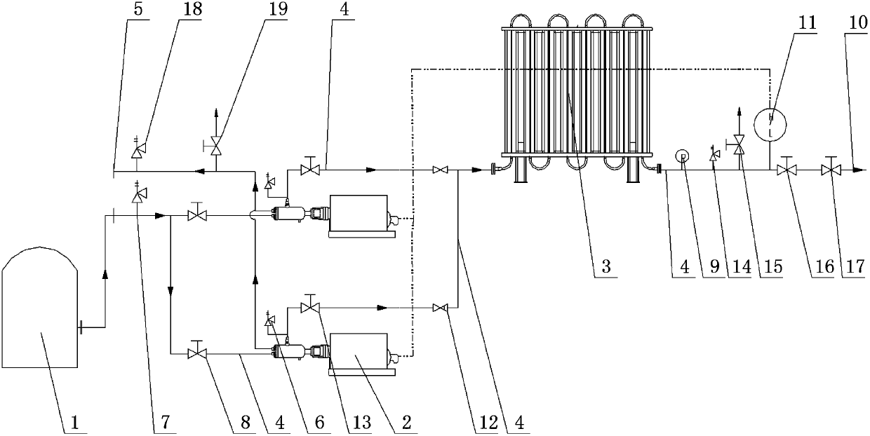
[0017] like figure 1 and 2 As shown, a natural gas delivery pipeline pressure test device of the present invention includes a cryogenic liquid storage tank 1, a cryogenic liquid pump 2 and an air-temperature vaporizer 3, and the cryogenic liquid storage tank 1 is connected to the cryogenic liquid pump through a pipe 4 2. The cryogenic liquid pump 2 is provided with a safety valve I6, and the pipe 4 between the cryogenic liquid storage tank 1 and the cryogenic liquid pump 2 is provided with a safety valve II7 and a low-temperature long-axis stop valve 8. The safety valve II7 is close to the end of the low-temperature liquid storage tank 1, and the low-temperature long-axis cut-off valve 8 is close to the end of the low-temperature liquid pump 2. The low-temperature liquid pump 2 is respectively connected to the air return port 5 and the air-temperature vaporizer 3 through the pipe 4. The pipe 4 between the gas port 5 and the cryogenic liquid pump 2 is provided with a safety va...


PUM


Abstract

The invention discloses a natural gas conveying pipe system pressure test device comprising a cryogenic liquid storage tank, cryogenic liquid pumps and an air-heated vaporizer, wherein the cryogenic liquid storage tank is connected with the cryogenic liquid pumps through a pipe, the cryogenic liquid pumps are respectively connected with an air return port and the air-heated vaporizer through a pipe, and the air-heated vaporizer is connected with a gas utilization point through a pipe. The natural gas conveying pipe system pressure test device has the following advantages: high-voltage test on a system can be completed in a short time, the test safety is high, tightness test can be immediately carried out, the test cycle is shortened, and cost is saved.

Description

technical field [0001] The invention relates to a pressure test device for a natural gas transmission pipeline system. Background technique [0002] At present, the known strength test process of liquefied natural gas and natural gas high-pressure pipeline system uses water or dry air as the test medium, but the subsequent drying process takes a long time when water is used as the test medium, and it is difficult to completely remove The water stored in the system, some equipment needs to be isolated during the test. Testing with dry air requires higher air quality, and high test pressure (25.5 Mpa) requires large compressors and auxiliary equipment, especially for systems with larger volumes, which require more equipment. It is more difficult to test the system with complex system and many welded valve parts. [0003] Therefore, there is an urgent need for an improved technology to solve this problem in the prior art. Contents of the invention [0004] The invention pr...

Claims


Application Information

Patent Timeline
Patent Type & Authority Applications(China)
IPC IPC(8): G01M99/00
Inventor 姚宁张林孟昌顺刘园元
Owner 南通中集太平洋海洋工程有限公司
Why Eureka
Try Eureka