

Direct insertion clip-shaped self-locking terminal
A terminal, self-locking technology, applied in the direction of fastening/insulating connectors, contact parts, electrical components, etc., can solve the problems of insufficiency and the unstable function of the shrapnel, and achieve the effect of uniform coating
- Summary
- Abstract
- Description
- Claims
- Application Information
AI Technical Summary
Problems solved by technology
Method used
Image

Examples
Embodiment 1
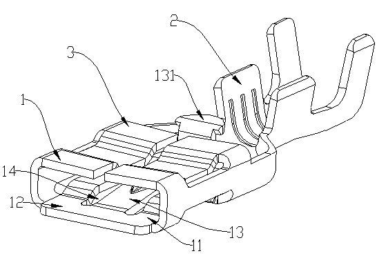
[0029] The in-line clip-shaped self-locking terminal of the present invention includes a cable connection part 2 and a wiring female terminal 3. The cable connection part 2 is clip-shaped, and the insertion direction on the cable connection part 2 is Consistent with the insertion direction of the female wiring terminal 3, fixing parts are respectively formed on both sides of the bottom surface of the cable connecting part 2, and the fixing parts are pressed to deform and fix the cable. The female wiring terminal 3 includes a slot 1. The upper part of the vertical side walls on both sides of the slot 1 is connected with two elastic planes respectively extending to the middle and used to cover the male terminal. The connection between the two elastic sheets 13 and the vertical side walls on both sides A rectangular notch is cut at the position. Corresponding to the notch, a downwardly recessed recess is formed on the elastic plane, and the recess is used to limit the movement spa...
Embodiment 2
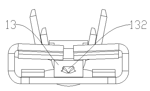
[0031] On the basis of the in-line clip-shaped self-locking terminal described in Embodiment 1, the elastic piece 13 is formed with a locking part on the inner side of the slot 1, and the locking part is a protrusion 132, and the protrusion 132 extends smoothly along the insertion direction, and the protrusion 132 can be correspondingly snapped into the hole of the male connection terminal, so that the male connection terminal is locked. Without pressing the pressing end 131, the male connection terminal will not easily Shedding ensures stability during use.
[0032]There is a gap 14 between the projection of the elastic sheet 13 on the slot bottom 11 and the slot bottom 11, and the gap 14 is preferably 0.36 mm on one side, which can ensure that the coating is uniformly and completely plated on the elastic sheet 13. On the sheet 13, the area of the slot bottom 11 will not be too small because the gap 14 is too large. As other convertible implementations, the gap 14 can also ...
PUM
 Abstract
Description
Claims
Application Information