Automatic centering support bracket in heat exchange tube

A technology of heat exchange tube and support frame, which is applied in the directions of heat transfer modification, heat exchange equipment, cleaning heat transfer device, etc., can solve the problems of strengthening heat transfer device failure, shortening the life of rotating shaft, unable to guarantee the center, etc., and prolonging the life. , the effect of reducing friction and reducing fluctuations

Inactive Publication Date: 2010-09-15
BEIJING UNIV OF CHEM TECH
View PDF10 Cites 3 Cited by
  • Summary
  • Abstract
  • Description
  • Claims
  • Application Information

AI Technical Summary

Problems solved by technology

However, because the heat exchange tube is generally long, the shaft of the fixed rotor cannot be well centered in the middle of the heat exchange tube, and there will be a little swing, which will shorten the life of the shaft. Heat transfer device failure

Method used


Image

  • Automatic centering support bracket in heat exchange tube
  • Automatic centering support bracket in heat exchange tube
  • Automatic centering support bracket in heat exchange tube

Examples


Embodiment Construction

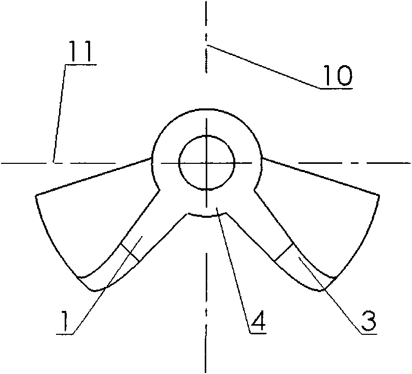
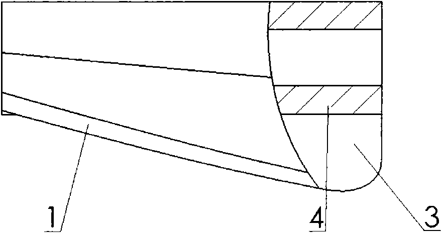
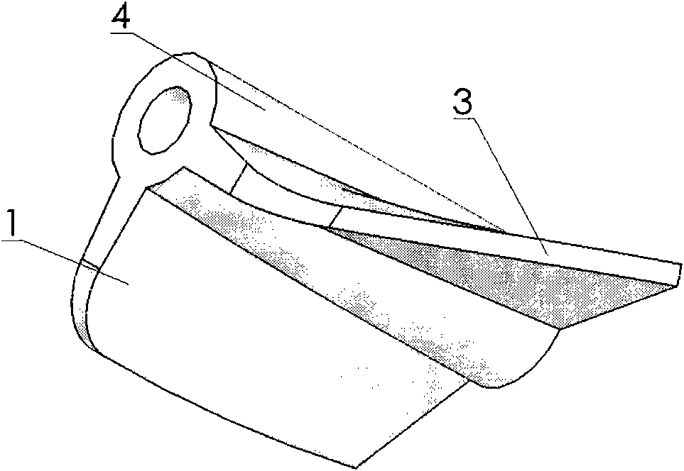
[0022] Figure 8 Shown is an implementation example of the application of the automatic centering support frame in the heat exchange tube of the present invention. In the figure, the enhanced heat transfer and online automatic anti-scaling and descaling device include the automatic centering support frame in the heat exchange tube of the present invention, the pendant 5, the rotating shaft 6, The rotor 7, the heat exchange tube 8 and the limiter 9, the support frame is mounted on the rotating shaft 6, located in the middle of the rotor 7, and several rotors 7 are mounted on the rotating shaft 6 between the two pendants 5, the The pendant 5 is fixed on both ends of the heat exchange tube 8, the two ends of the rotating shaft 6 are respectively fixed on the pendant 5, and the support frame is composed of the left blade 1, the middle blade 2 and the right blade 3 fixed on the hollow shaft 4 of.

[0023] Figure 1 to Figure 7 Shown are several structural forms of the self-center...


PUM


Abstract

The invention provides an automatic centering support bracket in a heat exchange tube, comprising a hollow shaft, a left blade and a right blade. The internal diameter of the hollow shaft is slightly larger than the external diameter of a rotating shaft, and the external diameter of the hollow shaft and the internal diameter of the heat exchange tube can be used to form concentric circles; the left blade and the right blade are in the convex edge structure which is fixed on the hollow shaft; the diameter of a cylinder which is formed by taking the center of the internal diameter of the hollow shaft as the center of a circle and the distance between the center of the internal diameter of the hollow shaft and the outer edge of the convex edge structure as the radius is equal to the internal diameter of the heat exchange tube; the left blade is symmetrical to the right blade relative to a central plane which penetrates through the hollow shaft; and the angle between the central plane and the plane which is formed by all the points of the outer edges of both the left blade and the right blade and the center line of the hollow shaft is an acute angle. The automatic centering support bracket is arranged in the heat exchange tube for a heat exchanger so that the rotating shaft and a rotor are in the center of the heat exchange tube, rotate stably, deflect less and reduce the friction. The left blade and the right blade of the automatic centering support bracket have the direction of rotating so that the fluid is increased in the turbulivity and has the effect of strengthening the heat transfer and preventing and removing the scale.

Description

technical field [0001] The invention relates to an auxiliary element used in heat transfer tubes in heat exchange tubes of equipment such as shell-and-tube heat exchangers, heat exchange reactors, etc., for enhancing heat transfer and antifouling and decontamination. Background technique [0002] With the continuous progress of society, energy saving and emission reduction in today's society is a key technology that the whole world attaches great importance to, especially in many fields such as petroleum, chemical industry, thermal power, nuclear power, metallurgy, light industry, aviation devices and ship vehicles. It is applied to many heat exchangers, among which the shell and tube heat exchanger is the most widely used, but the inner wall of the heat exchange tubes of these heat exchangers generally has layered fouling, which leads to an increase in the resistance of the fluid in the pipeline, which seriously Sometimes the pipes will be blocked, and the heat transfer per...

Claims


Application Information

Patent Timeline
Patent Type & Authority Applications(China)
IPC IPC(8): F28G15/02F28F13/12
Inventor 丁玉梅赵本华阎华何雪涛杨卫民
Owner BEIJING UNIV OF CHEM TECH
Why Eureka
Try Eureka