Method for fatigue assessment of rolling bearing

一种滚动轴承、疲劳的技术,应用在测试滚动轴承的装配配置领域,达到加速开始和发展、快速预测和相关对比、高接触应力的效果

Inactive Publication Date: 2014-04-23
AB SKF
View PDF4 Cites 4 Cited by
  • Summary
  • Abstract
  • Description
  • Claims
  • Application Information

AI Technical Summary

Problems solved by technology

In other words, even with accelerated techniques, a relatively large number of bearings must be tested over a relatively long period of time in order to obtain a valid bearing life estimate, where the cost of testing approaches the cost of manufacturing a test sample of the bearing

Method used


Image

  • Method for fatigue assessment of rolling bearing
  • Method for fatigue assessment of rolling bearing
  • Method for fatigue assessment of rolling bearing

Examples


Embodiment Construction

[0038] In the figures, similar or identical elements are denoted by the same reference numerals. The drawings are merely schematic representations, not true to scale and should not be considered as limiting the scope of the invention.

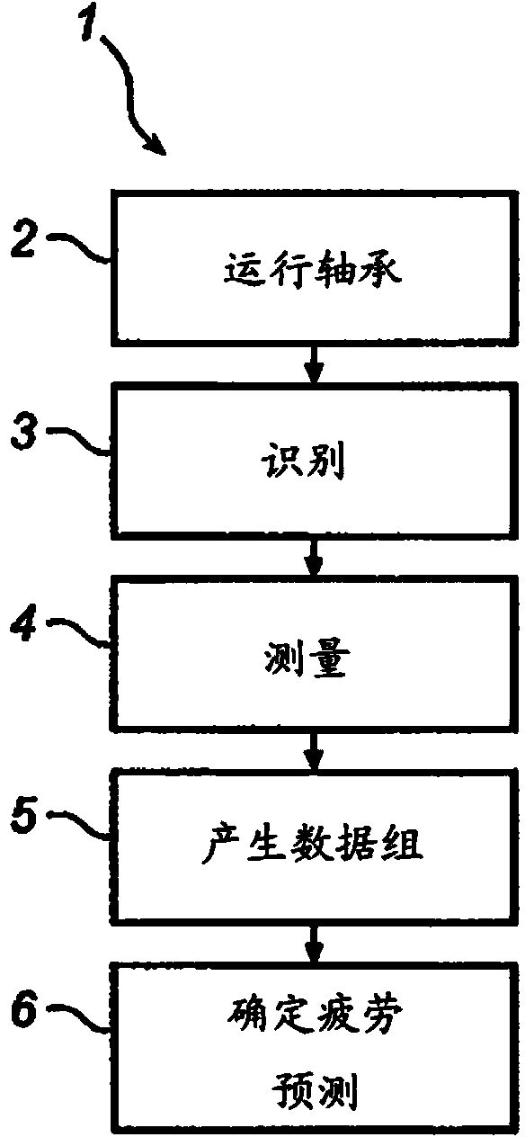
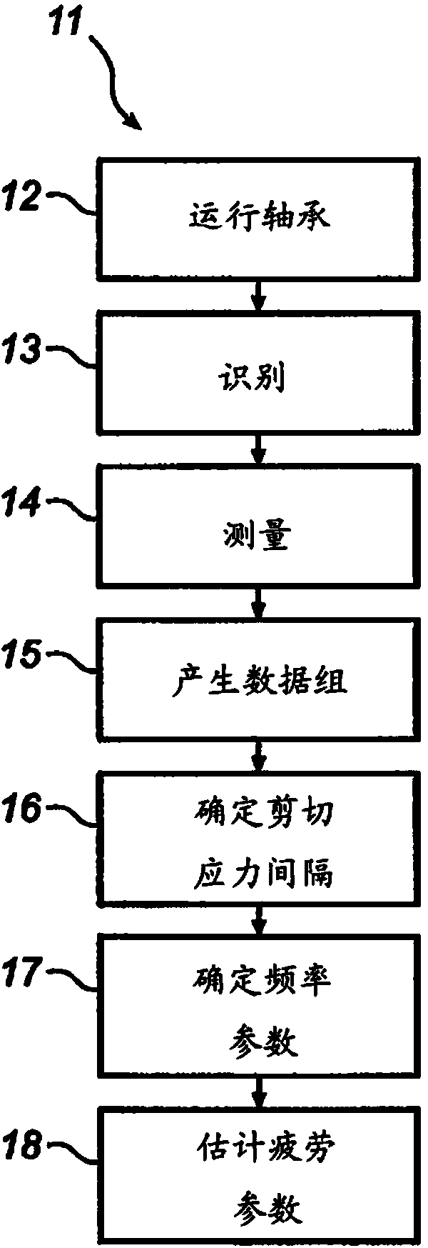
[0039] exist Figure 1a In to b, the schematic flow chart represents two different method embodiments 1 and 11 according to the invention. refer to Figure 1a , in Initial Running Bearing Step 2, the test bearing is run in a test rig, such as the SKF R-2 testing machine, where the test bearing is subjected to mechanical loads that produce subsurface changes in the raceway contact zone. The contact zone is formed by a three-dimensional volume of raceway material, which is subjected to internal and shear stress conditions that are created and initiated at, for example, point-like rolling contact surfaces between spherical rolling elements and raceways. Typically, test bearings are run until fracture or subsurface initiation fatigue failure occur...


PUM


Abstract

The present invention relates to a method, and an apparatus arrangement, for determining a fatigue limit for rolling contact initiated fatigue of a rolling bearing. The method comprises running a rolling bearing while being exerted to a load which generates sub-surface transformations in a rolling element contact zone of the outer or inner ring. Furthermore a set of sub-surface transformations in the contact zone along a raceway portion of the rolling bearing is identified and measured and used for generation of a parameter data set, wherein a fatigue parameter value representative of a predicted fatigue limit for the rolling bearing is determined based on the generated data set of sub-surface transformations.

Description

technical field [0001] The invention relates to a method or test method for determining the fatigue limit at which the rolling contact of a rolling bearing begins to fatigue. The method includes operating a rolling bearing comprising a plurality of rolling elements arranged between an outer ring and an inner ring, while the rolling bearing is loaded, which produces subsurface variations in rolling element contact zones of the outer ring or inner ring. [0002] The invention also relates to an assembly arrangement for testing a rolling bearing for determining the fatigue limit at which rolling contact fatigue begins, wherein the assembly arrangement comprises a test device for operating the rolling bearing, the test device being arranged to apply a load on the rolling bearing so as to exert a load on the rolling bearing Subsurface variations occur in the rolling element contact zone of the outer or inner ring. [0003] The method and the equipment arrangement according to the ...

Claims


Application Information

Patent Timeline
Patent Type & Authority Applications(China)
IPC IPC(8): G01M13/04F16C19/00
CPCF16C19/522G01M13/04F16C23/086G01M13/045G01N3/24F16C33/40F16C33/416F16C19/52F16C19/183
Inventor T.伦德K.赖登
Owner AB SKF
Why Eureka
Try Eureka