Fundus scanning imaging device

A technology of scanning imaging and imaging optics, which is applied in ophthalmoscopes, eye testing equipment, medical science, etc., can solve the problem of image resolution reduction and achieve the effects of saving system space, easy control, and eliminating eccentricity errors

Active Publication Date: 2014-04-30
SUZHOU MICROCLEAR MEDICAL INSTR
View PDF13 Cites 42 Cited by
  • Summary
  • Abstract
  • Description
  • Claims
  • Application Information

AI Technical Summary

Problems solved by technology

This patent uses incoherent line light sources such as halogen lamps or LEDs, and cooperates with line array receiving devices, and uses a single vibrating mirror to scan line by line in a direction perpendicular to the line array devices to obtain images of the entire fundus, but this technology Significantly lower image resolution compared to confocal laser techniques

Method used


Image

  • Fundus scanning imaging device
  • Fundus scanning imaging device
  • Fundus scanning imaging device

Examples


Embodiment Construction

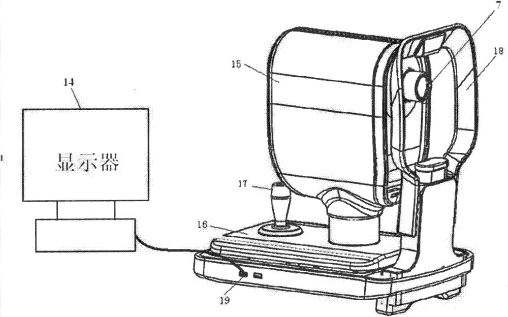
[0034] The mechanical structure of the fundus scanning imaging device in the present invention includes a main body shell 15, a moving base 16, a control handle 17, a chin rest 18, a signal output interface 19 and an external display device 14. The outline structure of the fundus scanning imaging device is as follows figure 1 .

[0035] The main body shell 15 contains the optical system and the signal acquisition and processing circuit in the fundus imaging device. The chin rest 17 is used to support and fix the subject's head. When the subject puts the head on the chin rest, the eyes should be at the same height as the eyepiece 7 . The motion base 16 provides support and adjustment for the three-dimensional motion of the main body shell 15 . The operator moves the main body 15 to align it with the eyes of the person to be tested, and the operator controls the handle 17 to complete the functions of focusing and taking pictures. The fundus imaging device is connected to an ex...


PUM


Abstract

The invention discloses a fundus scanning imaging device which is used for fundus examination of a human eye medically. A human eye fundus image is obtained through a confocal scanning technology to judge the fundus pathology and focus. The fundus scanning imaging device adopts laser as a lighting source. A scanning galvanometer achieves two-dimensional scanning of the human eye fundus. A high-sensitivity photodiode is used for detecting light signals returned from the human eye fundus, the collected signals are subjected to signal conversion and image reconstruction to obtain a large-view-field high-resolution fundus retina video image. The fundus scanning imaging device adopts a single galvanometer to replace a traditional orthogonal double-galvanometer module and acquires high-frame-frequency video image outputting through low galvanometer scanning frequency. A single detector is adopted, and a motor is utilized to switch an optical filter to achieve an FFA and ICGA fluorescent radiography function. Two kinds of retina images of light sources with different wavelengths can be utilized to combine a pseudo color image by synchronously controlling the image collection sequence, and two functions of video and camera shooting can be achieved simultaneously.

Description

technical field [0001] The invention relates to a fundus scanning imaging device, in particular to a large-field laser scanning fundus imager based on the principle of laser confocal, which uses laser light as an illumination source, and places a pinhole in front of a photodetector to realize the connection between the light source and the retina of the human eye. Confocal point-to-point imaging, the scanning galvanometer performs point-by-point two-dimensional optical scanning of the retina, and the obtained signals are collected and processed to reconstruct a real-time, high-resolution human retinal scanning image and output it in the form of video through the display . Background technique [0002] Confocal microscopy was proposed by Marvin Minsky in 1957, and the first commercial confocal microscope was launched by BIO-RAD in 1987. So far, confocal microscopy has been widely used in the field of biomedicine. Confocal imaging is an optical method that uses point-by-poin...

Claims


Application Information

Patent Timeline
Patent Type & Authority Applications(China)
IPC IPC(8): A61B3/12A61B3/14
Inventor 李研张锐进李超宏
Owner SUZHOU MICROCLEAR MEDICAL INSTR
Why Eureka
Try Eureka