High-power and high-speed electric spindle

A high-speed electric spindle and high-power technology, applied in the direction of large-scale fixed members, clamping, support, etc., can solve the problems of limited effect, limited cooling effect, high performance requirements of lubricating grease, etc., to achieve enhanced lubrication effect, improve rotation efficiency, Avoid the effect of taking off the knife

Active Publication Date: 2014-04-30
GUANGZHOU HAOZHI ELECTROMECHANICAL
View PDF4 Cites 9 Cited by
  • Summary
  • Abstract
  • Description
  • Claims
  • Application Information

AI Technical Summary

Problems solved by technology

[0005] At present, the high-speed rotation of the electric spindle mainly depends on the upper bearing and the lower bearing matched by the upper bearing seat and the lower bearing seat at both ends of the shaft core. The inner ring and the outer ring of the upper bearing and the lower bearing are filled with lubricating oil to ensure that the electric spindle The shaft core rotates at high speed. This method of lubrication has high requirements on the performance of the grease, and the lubricating effect of the grease is not ideal after a long time of use, which affects the rotation speed of the electric spindle. In order to improve the rotation e

Method used


Image

  • High-power and high-speed electric spindle
  • High-power and high-speed electric spindle
  • High-power and high-speed electric spindle

Examples


Embodiment Construction

[0037] Below, in conjunction with accompanying drawing and specific embodiment, the present invention is described further:

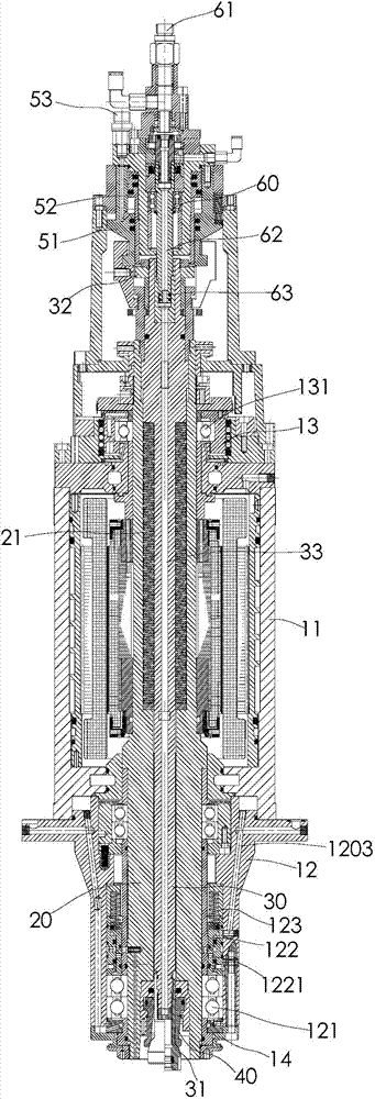
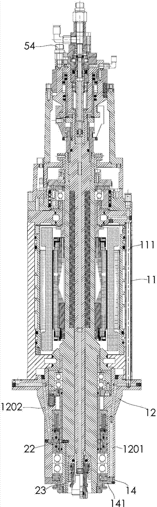
[0038] Such as figure 1 and figure 2As shown, the high-power high-speed electric spindle of the present invention includes a body assembly, a shaft core 20, a pull claw 40, a pull rod 30, a rotary joint assembly and an air blowing channel, and the body assembly includes a body 11 and an upper bearing installed on the top of the body 11 The seat assembly 13 , the lower bearing seat assembly 12 installed on the lower part of the machine body 11 and the end cover 14 connected to the lower end of the lower bearing seat assembly 12 . The shaft core 20 is connected to the inside of the machine body 11, its upper end is pivotally connected to the upper bearing seat assembly 13 through the upper bearing 131, and its lower end is pivotally connected to the lower bearing seat assembly 12 through the lower bearing 121, and the lower end of the shaft core 20 pass...


PUM


Abstract

The invention discloses a high-power and high-speed electric spindle. The high-power and high-speed electric spindle comprises a body assembly, a spindle core, a pull claw and a pull rod, wherein the body assembly comprises a body, an upper bearing seat component and a lower bearing seat component; the upper end of the spindle core is pivoted with the upper bearing seat component through an upper bearing; the lower end of the spindle core is pivoted with the lower bearing seat component through a lower bearing; the pull claw is mounted on the lower end of the spindle core and connected with a cutter; a lower bearing oil-gas inlet channel and a lower bearing oil-gas outlet channel are formed in the body; an inner side end of the lower bearing oil-gas inlet channel is communicated with a gap between an inner ring and an outer ring of the lower bearing; an inner side end of the lower bearing oil-gas outlet channel is communicated with the gap between the inner ring and the outer ring of the lower bearing; an upper bearing oil-gas inlet channel and an upper bearing oil-gas outlet channel are also formed in the boy; an inner side end of the upper bearing oil-gas inlet channel is communicated with the gap between the inner ring and the outer ring of the upper bearing; and an inner side end of the upper bearing oil-gas outlet channel is communicated with the gap between the inner ring and the outer ring of the upper bearing. According to the high-power and high-speed electric spindle, inner rings and outer rings of the upper bearing, the lower bearing and the middle bearing of the electric spindle are lubricated by using an oil-gas lubrication medium, so that the lubrication effect is improved and the rotation efficiency of the electric spindle center is improved.

Description

[0001] technical field [0002] The invention relates to a high-power high-speed electric spindle used in the field of mechanical processing [0003] Background technique [0004] The electric spindle is a commonly used equipment for mechanical processing. It usually includes the body and the shaft core assembly. The shaft core assembly is installed inside the body. The shaft core assembly rotates at high speed, and an upper bearing seat and a lower bearing seat are fixed on the body, and the two ends of the shaft core assembly are pivotally connected to the upper bearing seat and the lower bearing seat through the upper bearing and the lower bearing respectively. [0005] At present, the high-speed rotation of the electric spindle mainly depends on the upper bearing and the lower bearing matched by the upper bearing seat and the lower bearing seat at both ends of the shaft core. The inner ring and the outer ring of the upper bearing and the lower bearing are filled with lu...

Claims


Application Information

Patent Timeline
IPC IPC(8): B23B19/02B23Q11/12B23Q3/157
CPCB23Q11/123B23Q5/10B23Q1/70
Inventor 汤秀清
Owner GUANGZHOU HAOZHI ELECTROMECHANICAL
Why Eureka
Try Eureka