
Inlaid bearing inner wall blind hole lathe drilling power unit

A technology for power devices and blind holes, applied in boring/drilling devices, metal processing equipment, drilling/drilling equipment, etc., can solve problems such as unrealizable, and achieve the effects of easy maintenance, simple structure, and convenient operation

Inactive Publication Date: 2016-06-08
SHANGHAI INST OF TECH
View PDF7 Cites 0 Cited by
  • Summary
  • Abstract
  • Description
  • Claims
  • Application Information

AI Technical Summary

Problems solved by technology

Obviously, it is impossible to achieve the blind hole drilling process on the inner wall of the embedded bearing on the existing lathe

Method used


Image

  • Inlaid bearing inner wall blind hole lathe drilling power unit
  • Inlaid bearing inner wall blind hole lathe drilling power unit
  • Inlaid bearing inner wall blind hole lathe drilling power unit

Examples


Embodiment Construction

[0014] The present invention will be further described below in conjunction with the accompanying drawings and embodiments.

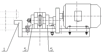
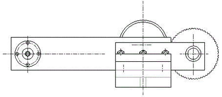
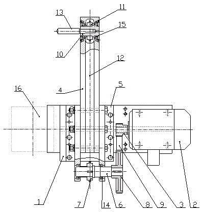
[0015] Such as Figure 1 to Figure 3 As shown, a power device for drilling a blind hole lathe with an inlaid bearing inner wall, including a bracket base 1, a motor 2, a small pulley 3, a knife plate 4, a fixed angle frame 5, a spindle 6, a sprocket 7, and a large pulley 8. Timing belt 9, Morse taper shaft 10, sprocket 11, chain 12, drilling tool 13, angular contact bearing 14, tapered roller bearing 15, lathe tool rest 16.

[0016] The bracket base 1 is installed on the lathe tool holder 16 and fixed by locking bolts. The motor 2 is installed on the bracket base 1. The small pulley 3 is connected to the output shaft of the motor 2. The large pulley 8 is connected to the small pulley 3 through the timing belt 9. Connection, the output shaft end of the mandrel 6 is connected with the large pulley 8, a pair of angular contact bearings 14 are installed on...


PUM


Abstract

The invention relates to a power device of a lathe for drilling blind holes in the inner walls of embedded bearings. A lathe knife rest is fixedly connected with a support base which is provided with a motor, an output shaft of the motor is connected with a small belt wheel, the small belt wheel is in transmission connection with a large belt wheel at the output shaft end of a mandrel through a synchronous belt, the mandrel is arranged at the rear end of a knife blade through a pair of angular contact bearings, the middle of the mandrel is fixedly connected with a chain wheel, the knife blade is connected with the support base through two fixed corner brackets, a Mohs taper sleeve shaft is arranged at the cantilever end of the knife blade through a pair of conical bearings, the middle of the Mohs taper sleeve shaft is fixedly connected with another chain wheel, one chain wheel is connected with the other chain wheel through a chain in a transmission mode, and a drilling tool is connected inside the Mohs taper sleeve shaft in a matched mode. According to the power device, when the lathe is used for drilling the blind holes in the inner walls of the embedded bearings, the axis of the tool and the axes of the embedded bearings are in a right-corner state, and the machining tool conducts rotational motion. A large carriage is moved so as to conduct axial locating of the distances between the blind holes in the inner walls of the embedded bearings, a middle carriage is moved in the radial direction so as to control the depths of the machined blind holes, and therefore it is achieved that the lathe is used for drilling the blind holes in the inner walls of the embedded bearings.

Description

technical field [0001] The invention relates to a drilling power device for machining a blind hole on the inner wall of an inlaid bearing with a lathe, in particular to a device suitable for drilling blind holes with a diameter of ≥¢200 mm on the inner wall of an inlaid bearing. Background technique [0002] It is impossible to drill the blind hole on the inner wall of the inlaid bearing on the lathe. Because the chuck of the lathe can fix the workpiece, it can also drive the workpiece to rotate and index. The processing tool on the tool rest on the carriage moves in a straight line, and the processing tool on the tool rest on the carriage in the lathe only moves in a straight line. For the processing of the blind hole on the inner wall of the inlaid bearing, it is hoped that the chuck of the lathe can clamp the workpiece to fix the positioning and indexing, the large carriage of the lathe can be used for linear positioning, the middle carriage of the lathe can be used for l...

Claims


Application Information

Patent Timeline
Patent Type & Authority Patents(China)
IPC IPC(8): B23B43/00B23B47/06
CPCB23B43/00
Inventor 沈秀国侯月培陆保康徐家跃
Owner SHANGHAI INST OF TECH
Learn More