Shaft hugging box withdrawing machine

A shaft holding box and unloading machine technology, applied in metal processing, metal processing equipment, manufacturing tools, etc., can solve the problems of mechanical backwardness, manual unloading, and potential safety hazards, and achieve high work efficiency, high degree of automation, The effect of simple and convenient operation

Active Publication Date: 2014-04-30
HUBEI HEQIANG MACHINERY DEV LIMITED BY SHARE
View PDF9 Cites 4 Cited by
  • Summary
  • Abstract
  • Description
  • Claims
  • Application Information

AI Technical Summary

Problems solved by technology

[0002] With the speed of trains being increased many times, especially in recent years to adapt to the rapid development of the railway passenger and freight transportation market, the construction of high-speed railways has started, and the high-speed electric locomotives with a speed of 200km / h have been put into operation, and the mechanical requirements for railway rolling stock equipment are getting higher and higher. , in order to meet the new requirements, various new technologies and new products such as manufacturing, press-fitting and unloading of the wheel set are constantly emerging, while the unloading of the axle box on the wheel set is relatively backward, and some use manual The method of unloading, some machines are simple and backward
At present, there is a model in the market that puts the wheelset upright, fixes the axle holding box at the bottom, and separates the axle from the box by pulling the axle from above. The process requires the help of multiple people to complete, and most importantly, one axis is independent, which is daunting and poses a safety hazard

Method used


Image

  • Shaft hugging box withdrawing machine
  • Shaft hugging box withdrawing machine
  • Shaft hugging box withdrawing machine

Examples


Embodiment Construction

[0018] The present invention will be further described below in conjunction with the accompanying drawings.

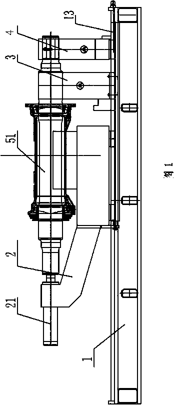
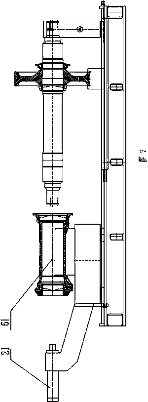
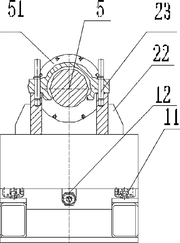
[0019] Such as Figure 1 to Figure 10 As shown, the present invention discloses a shaft holding box unloading machine, which includes a base 1, an unloading device 2, a hydraulic system, and an electrical control system. The base 1 is provided with a B-shaped unloading device 2 , a main oil cylinder 21 is provided on the head of the letter B, a box seat 22 is provided on the belly of the letter B, a pin hole corresponding to the axle box is provided on the box seat, and a guide rail 11 is provided on the base under the letter B And the long oil cylinder 12, on the right side of the machine base is provided with a supporting shaft seat 3 and a locking seat 4, and the locking seat is provided with a lifting device 41B, which is convenient for height adjustment and adapts to the needs of different wheelsets; The supporting shaft seat is fixed on the machine base, and the...


PUM


Abstract

The invention discloses a shaft hugging box withdrawing machine which comprises a machine seat, a withdrawing device, a hydraulic system and an electric control system. The withdrawing device which is in the shape of a Z is arranged on the machine seat, a main oil cylinder is arranged at the head of the Z, supporting box seats are arranged at the belly of the Z, an inserting pin hole corresponding to a shaft hugging box is arranged on each supporting box seat, guide rails and a long oil cylinder are arranged on the machine seat under the Z, a supporting shaft seat and a locking seat are arranged on the right side of the machine seat, a lifting device is arranged in the locking seat, the supporting shaft seat is fixed above the machine seat, a lead screw is arranged on the machine seat below the locking seat, and a locking device is arranged on the locking seat. The shaft hugging box withdrawing machine has the advantages that mechanical and automatic level of withdrawing is high; after a workpiece is placed on the machine, the whole withdrawing process can be completed only by one person, so that time and labor are saved, and working efficiency is high; an electromechanical-hydraulic centralized control mode is adopted, so that the machine is simple and convenient to operate; due to horizontal withdrawing, safety and reliability are realized.

Description

technical field [0001] The invention relates to equipment machinery for railway locomotives, which is suitable for withdrawing and unloading axle-holding boxes of train wheels. Background technique [0002] With the train speeding up many times, especially in recent years, in order to adapt to the rapid development of the railway passenger and freight transportation market, the construction of high-speed railways has started, and the high-speed electric locomotives with a speed of 200km / h have been put into operation, and the mechanical requirements for railway rolling stock equipment are getting higher and higher. , in order to adapt to the new requirements, various new technologies and new products are constantly emerging for the manufacture, press-fitting and unloading of the wheel set, while the unloading of the axle box on the wheel set is relatively backward, and some use manual The method of unloading is simple and backward in some machines. At present, there is a mo...

Claims


Application Information

Patent Timeline
Patent Type & Authority Applications(China)
IPC IPC(8): B23P19/00
CPCB23P19/025B23P19/027
Inventor 喻国锋范鸿童俊军张霄喻侃童光董婷婷吕志刚李昌齐
Owner HUBEI HEQIANG MACHINERY DEV LIMITED BY SHARE
Why Eureka
Try Eureka