
A solid tire dismounting and anti-tire structure

A solid tire and rim technology, applied in tire parts, rims, non-pneumatic tires, etc., can solve problems such as internal structure deformation, breaking, load-bearing frame and/or tire material damage, etc., to reduce installation weight, installation Easy to disassemble and versatile

Inactive Publication Date: 2016-05-04
李学恩
View PDF4 Cites 0 Cited by
  • Summary
  • Abstract
  • Description
  • Claims
  • Application Information

AI Technical Summary

Problems solved by technology

Solid tires are generally molded by casting the load-bearing frame and the tire material together. When installing the tire, it is necessary to use tools to pull the diameter of the solid tire larger than the rim to install the rim, so it is easy to cause damage to the load-bearing frame and / or tire material, such as solid tire hoops The steel wire is easily broken during installation due to its lack of elasticity
Once the load-bearing frame and / or tire material is damaged, the entire tire has to be replaced, resulting in waste of material
[0004] In addition, existing solid tires all have the problem of bodiless, the main reasons are: 1 when the temperature of the solid tire material changes, the material will soften and cause bodiless
2. When the solid tire is impacted by external forces such as braking and load, it will cause the tire to fall out
3. Solid tires are only equipped with steel wires for positioning, and there is no clamping device, which cannot achieve the clamping effect between the tire and the hub.
4. When the solid tire is stretched by tools during installation, the internal structure is deformed, resulting in bodiless

Method used


Image

  • A solid tire dismounting and anti-tire structure
  • A solid tire dismounting and anti-tire structure
  • A solid tire dismounting and anti-tire structure

Examples


Embodiment 1

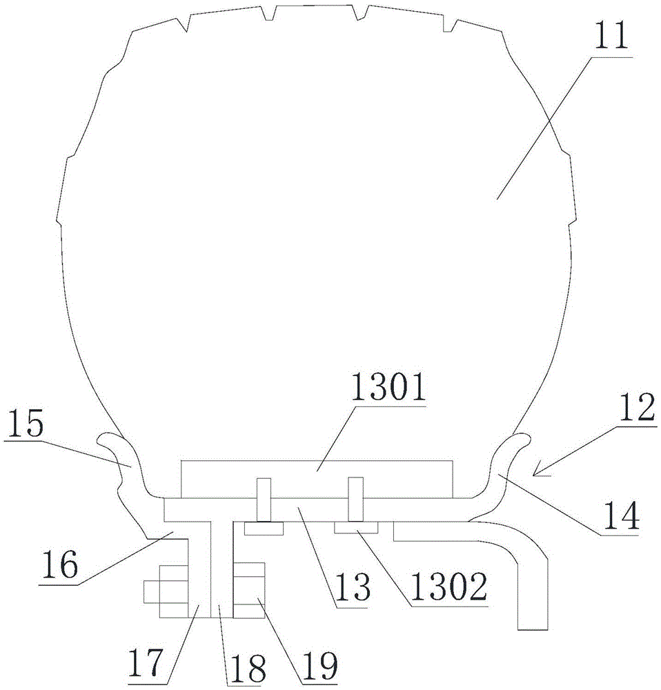
[0025] Such as figure 1 As shown, a solid tire assembly and detachment prevention structure includes a solid tire 11 and a rim 12, and the solid tire 11 is installed on the rim 12. The rim 12 includes a bead seat 13 , and rims are arranged on both sides of the bead seat 13 , one side is a fixed rim 14 and the other side is a detachable rim 15 . The fixed rim 14 is integrally connected with the bead seat 13, and the detachable rim 15 is connected with the bead seat 13 in a split type. The detachable rim 15 is connected to the rim extension ring 16, the detachable rim 15 is connected to the rim extension ring 16 in one piece, the rim extension ring 16 is connected to the extension ring flange 17, and the bead seat 13 is connected to the bead seat flange 18. The extension ring flange 17 is connected with the bead seat flange 18 through the anti-loosening bolt 19. Two stop blocks 1301 are symmetrically arranged on the bead seat 13 , and the stop blocks 1301 are fixed on the bead...

Embodiment 2

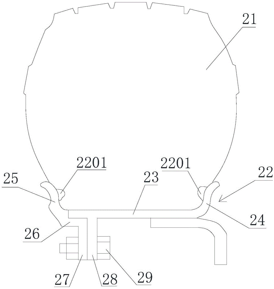
[0028] Such as figure 2 As shown, a solid tire dismounting and anti-tire structure includes a solid tire 21 and a rim 22, and the solid tire 21 is installed on the rim 22. The rim 22 includes a bead seat 23 , and rims are arranged on both sides of the bead seat 23 , one side is a fixed rim 24 and the other side is a detachable rim 25 . The fixed rim 24 is integrally connected with the bead seat 23 , and the detachable rim 25 is connected with the bead seat 23 in a split type. The detachable rim 25 is connected to the rim extension ring 26, and the detachable rim 25 is connected to the rim extension ring 26 in one piece, the rim extension ring 26 is connected to the extension ring flange 27, and the bead seat 23 is connected to the bead seat flange 28. The extension ring flange 27 is connected with the bead seat flange 28 through the anti-loosening bolt 29. Both the inner sides of the fixed rim 24 and the detachable rim 25 are provided with stop projections 2201, and the sto...

Embodiment 3

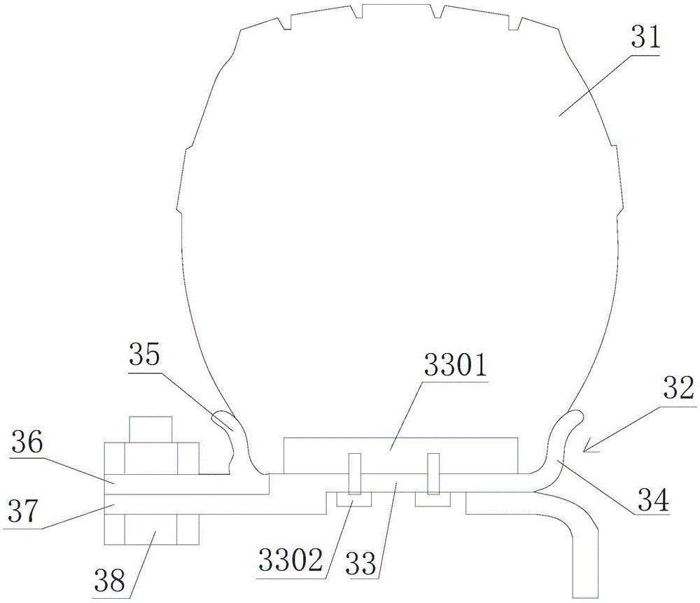
[0031] Such as image 3 As shown, a solid tire dismounting and anti-tire structure includes a solid tire 31 and a rim 32, and the solid tire 31 is installed on the rim 32. The rim 32 includes a bead seat 33 , and rims are arranged on both sides of the bead seat 33 , one side is a fixed rim 34 and the other side is a detachable rim 35 . The fixed rim 34 is integrally connected with the bead seat 33 , and the detachable rim 35 is connected with the bead seat 33 in a split type. The detachable rim 35 is connected to the rim extension ring 36, the bead seat 33 is connected to the bead seat extension ring 37, the bead seat extension ring 37 is arranged in parallel below the bead seat 33, and the bead seat extension ring 37 is connected to the bead seat Seats 33 are partially overlapped, and the two are connected in a stepped shape. The rim extension ring 36 is arranged closely above the bead seat extension ring 37 . The rim extension ring 36 is connected with the bead seat exten...


PUM


Abstract

The invention discloses a solid tire demounting and tire-dropping preventing structure which comprises a solid tire and a rim, wherein the solid tire is installed on the rim; the rim comprises a bead seat, wheel flanges are arranged on the two sides of the bead seat, and at least one wheel flange is detachably connected with the bead seat; the wheel flange detachably connected with the bead seat is connected with a wheel flange extending ring, the wheel flange extending ring is connected with an extending ring flange, the bead seat is connected with a bead seat flange, and the extending ring flange is connected with the bead seat flange through a bolt; or the wheel flange detachably connected with the bead seat is connected with the wheel flange extending ring, the bead seat is connected with a bead seat extending ring, and the wheel flange extending ring is connected with the bead seat extending ring through a bolt; a chock block is arranged on the bead seat, and a slot matched with the chock block is formed in the solid tire; and / or a stop bulge is arranged on each wheel flange, and a groove matched with the stop bulge is formed in the solid tire. The solid tire demounting and tire-dropping preventing structure can effectively solve the demounting and tire-dropping preventing problems of the solid tire.

Description

technical field [0001] The invention relates to a structure which facilitates disassembly and assembly of solid tires and can effectively prevent the solid tires from coming off, and belongs to the field of vehicle tires. Background technique [0002] Solid tires have excellent properties such as puncture resistance, high temperature resistance, wear resistance and no tire blowout. Even in harsh environments and heavy loads, they still maintain good performance, thus ensuring transportation safety. Although the price of solid tires is two to three times more expensive than pneumatic tires, its service life can reach four to six times that of pneumatic tires, and it avoids the trouble of repairing tires. Calculate the long-term use cost, solid tires can be doubled than pneumatic tires. [0003] Solid tires are technically mature and have the above-mentioned advantages, but the installation of solid tires is relatively difficult, and the performance of solid tires will inevita...

Claims


Application Information

Patent Timeline
Patent Type & Authority Patents(China)
IPC IPC(8): B60C7/00B60B25/20
Inventor 李学恩
Owner 李学恩
Learn More