
A corner transfer mechanism

A transmission mechanism and corner technology, applied in the direction of conveyor objects, transportation and packaging, etc., can solve the problems of low production efficiency, high maintenance costs, increased human resource costs, etc., and achieve the effect of strong practicability and simple structure

Inactive Publication Date: 2016-01-06
AD TOYO LIGHTING GUANGZHOU
View PDF6 Cites 0 Cited by
  • Summary
  • Abstract
  • Description
  • Claims
  • Application Information

AI Technical Summary

Problems solved by technology

[0002] In the production process, processed products often need to be transported between two production lines placed in different directions. If the operation is manually intervened, not only the production efficiency is not high, but also the cost of human resources will be increased. In addition, although there are mechanical Realize this operation, but its structure is complicated, the maintenance cost is high, and it is often tailor-made, resulting in too narrow application range

Method used


Image

  • A corner transfer mechanism

Examples


Embodiment

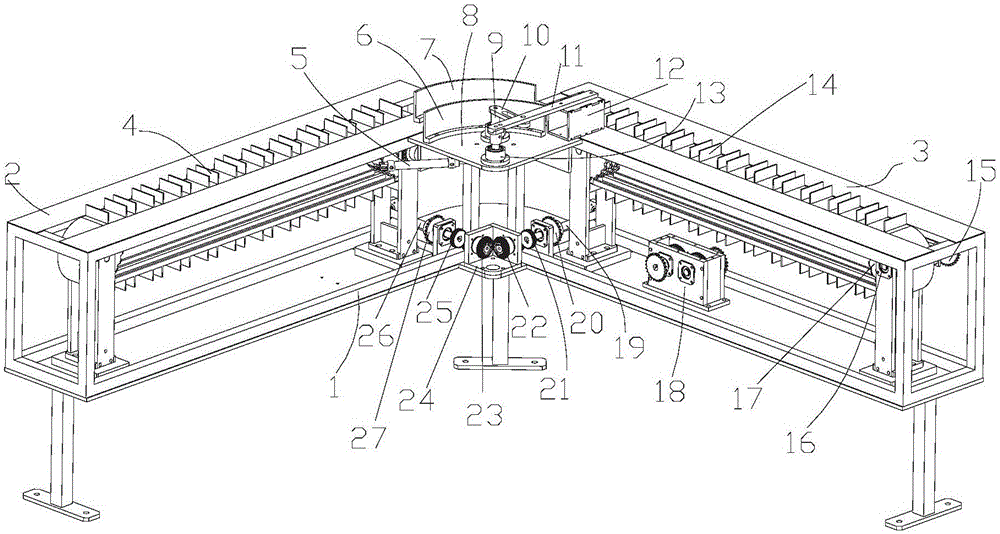
[0059] A corner transmission mechanism, including a control system (not shown), a frame 1, a motor 18, a first conveyor belt 14, a first drive device, a synchronization device, a second conveyor belt 4, a second drive device and a corner device;

[0060] Wherein, the control system is used to control the actions of the motor 18, the first conveyor belt 14, the synchronizing device, the second conveyor belt 4 and the corner device;

[0061] The frame 1 includes a first side 3, a second side 2, a first mounting plate 8 and a second mounting plate 24, the first side 3 and the second side 2 intersect, and the angle formed by them is adjustable; the second A mounting plate 8 and a second mounting plate 24 are located at the connecting portion of the first side 3 and the second side 2, the first mounting plate 8 is lower than the first conveyor belt 14 and the second conveyor belt 4, and the second mounting plate 24 is lower On the first mounting plate 8; the frame 1 is used to inst...


PUM


Abstract

The invention provides a corner conveying mechanism. The corner conveying mechanism comprises a control system, a frame, a motor, a first conveyor belt, a first driving device, a synchronization device, a second conveyor belt, a second driving device and a corner device; the frame comprises the first lateral side, the second lateral side, a first installing plate and a second installing plate; the first lateral side and the second lateral side intersect; the first installing plate and the second installing plate are located at the connection position of the first lateral side and the second lateral side; the motor is arranged on the frame and connected with the first driving device and the synchronization device; the first conveyor belt and the first driving device are arranged on the first lateral side; the second conveyor belt and the second driving device are arranged on the second lateral side; the synchronization device is arranged on the frame and connected with the second driving device; the corner device is arranged on the frame. According to the corner conveying mechanism, machined products can be conveyed between two production lines which are placed in different directions, the structure is simple, and the practicability is strong.

Description

technical field [0001] The invention relates to the field of automatic machinery, in particular to a corner transmission mechanism. Background technique [0002] In the production process, processed products often need to be transported between two production lines placed in different directions. If the operation is manually intervened, not only the production efficiency is not high, but also the cost of human resources will be increased. In addition, although there are mechanical Realize this operation, but its structure is complex, the maintenance cost is high, and it is often tailor-made, resulting in too narrow application range. [0003] It is not difficult to see that there are certain defects in the prior art. Contents of the invention [0004] The technical problem to be solved by the present invention is to provide a corner transmission mechanism, which can transport processed products between two production lines placed in different directions, and has the chara...

Claims


Application Information

Patent Timeline
Patent Type & Authority Patents(China)
IPC IPC(8): B65G47/52B65G47/22
Inventor 关崇安
Owner AD TOYO LIGHTING GUANGZHOU
Learn More