Single and double girder crane trolley of electric hoist

A double-girder crane and electric hoist technology, applied in the direction of traveling mechanism, load hanging components, transportation and packaging, etc., can solve the problems of high cost, not easy to control, and out-of-synchronization of wheels, so as to improve work efficiency and ensure Synchronization and cost reduction effects

Inactive Publication Date: 2014-04-30
陈高兵
View PDF0 Cites 6 Cited by
  • Summary
  • Abstract
  • Description
  • Claims
  • Application Information

AI Technical Summary

Problems solved by technology

The wheel sets of the current trolleys for cranes are driven by two motors respectively. This structure

Method used


Image

  • Single and double girder crane trolley of electric hoist

Examples


Example Embodiment

[0012] The technical solution of the present invention will be further specifically described below in conjunction with specific embodiments.

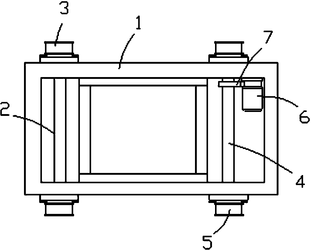
[0013] Such as figure 1 As shown, an electric hoist single and double beam crane trolley includes a frame 1. The front part of the frame 1 is connected with two No. 1 wheels 3 through a first rotating shaft 2, and the rear part of the frame 1 is connected with a second rotating shaft 4. Two second wheels 5, the second rotating shaft 4 is linked with the motor 6, the second rotating shaft 4 is connected with a gear 7, and the gear 7 meshes with the gear on the output shaft of the motor 6. The motor 6 is mounted on the frame 1 through a fixing plate. 6 Drives two No. 2 wheels 5 to run, which ensures the synchronization of the trolley during operation, does not deviate, and reduces manufacturing costs and improves work efficiency.

[0014] Finally, it should be noted that the above specific embodiments are only used to illustrate the technica...


PUM


Abstract

The invention relates to the technical field of cranes and discloses a single and double girder crane trolley of an electric hoist. The single and double girder crane trolley comprises a trolley frame, wherein the front part of the vehicle frame is connected with two driven wheels by virtue of a driven rotary shaft, the back part of the vehicle frame is connected with two driving wheels by virtue of a driving rotary shaft, and the driving rotary shaft is linked with a motor. As one motor drives the two driving wheels so as to drive the single and double girder crane trolley to run, the synchronism without off tracking of the trolley in the running process is ensured, the manufacturing cost is also lowered, and the working efficiency is improved.

Description

technical field [0001] The invention relates to the technical field of cranes, in particular to an electric hoist single- and double-girder crane trolley. Background technique [0002] With the vigorous development of my country's iron and steel industry, crane technology is also constantly improving. Cranes will be gradually put into use in more industries in the future to reduce the work intensity of personnel and increase work efficiency, which will inevitably affect the stability of cranes. Sexuality puts forward higher demands. Among the lifting equipment, the electric hoist bridge crane is widely used due to its compact size, light weight, and small wheel pressure. The wheel sets of the current trolleys for cranes are driven by two motors respectively. This structure easily leads to asynchronous operation of the wheels, which is not easy to control, and the cost is also high. Contents of the invention [0003] The technical problem to be solved by the present invent...

Claims


Application Information

Patent Timeline
IPC IPC(8): B66C9/10
Inventor 陈高兵
Owner 陈高兵
Why Eureka
Try Eureka