
Mounting structure for plate material fixing element for laminating machine as well as top plate and laminating machine

一种安装结构、固定件的技术,应用在层压装置、化学仪器和方法、层压辅助操作等方向,能够解决产品合格率下降、制造成本增加、玻璃板过压等问题,达到降低生产成本、提高合格率、避免过压现象的效果

Active Publication Date: 2014-04-30
TCL CHINA STAR OPTOELECTRONICS TECH CO LTD
View PDF6 Cites 2 Cited by
  • Summary
  • Abstract
  • Description
  • Claims
  • Application Information

AI Technical Summary

Problems solved by technology

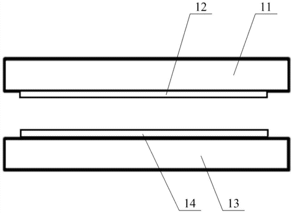
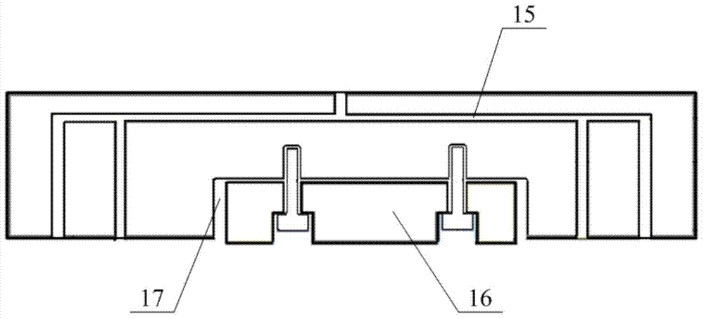
[0006] But plate fixing member 16 adopts this installation structure, when top plate 11 moves downward and upper glass plate 12 and lower glass plate 14 are pressed together, because the bottom end of plate fixing member 16 is positioned at the bottom of the bottom of top plate 11, will make The pressure of the glass plate at the plate fixing member 16 is too high to cause an overpressure phenomenon, which causes the glass plate to produce light spots, which in turn leads to a decline in the pass rate of the product and an increase in manufacturing costs

Method used


Image

  • Mounting structure for plate material fixing element for laminating machine as well as top plate and laminating machine
  • Mounting structure for plate material fixing element for laminating machine as well as top plate and laminating machine
  • Mounting structure for plate material fixing element for laminating machine as well as top plate and laminating machine

Examples


Embodiment 1

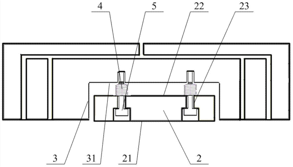
[0048] Such as image 3 with Figure 4 As shown, the installation structure of the plate fixing part 2 for the laminating machine provided in this embodiment includes a plate fixing part 2 and an installation groove 3 for installing the plate fixing part 2; the plate fixing part 2 is placed in the installation groove 3 and It can move vertically in the installation groove 3 , and an elastic reset member 4 is arranged between the plate fixing part 2 and the installation groove 3 .

[0049]Wherein, when the elastic restoring member 4 is stretched, the vertical first end portion 21 of the panel fixing member 2 extends to the vertical outer portion of the notch of the installation groove 3 .

[0050] When the first end portion 21 receives a pressure vertically toward the inside of the installation groove 3 , the plate fixing member 2 moves vertically toward the inside of the installation groove 3 and compresses the elastic reset member 4 .

[0051] In use, the elastic resetting ...

Embodiment 2

[0066] Such as Figure 5 with Image 6 As shown, the top plate for the laminating machine provided in this embodiment includes a plate body 6 and at least one installation structure of the plate fixing member 2 provided in the above-mentioned embodiment one provided on the plate body 6; wherein, the installation groove 3 Formed at the lower end portion of the plate body 6 in the vertical direction.

[0067] Further preferably, in order to ensure the stability of the connection between the upper glass plate and the top plate, a plurality of plate fixing parts 2 can be evenly distributed on the plate body 6. The installation structure can be referred to Figure 5 shown.

[0068] In this embodiment, when the upper glass plate is engaged with the plate fixing member 2 on the top plate, it can be lifted up by the mechanical arm. But further preferably, a vacuum suction port 61 may be formed at the vertical lower end of the plate body 6 , and a vacuum pipeline 62 communicating wi...

Embodiment 3

[0070] The laminating machine provided in this embodiment includes a bottom plate and a top plate for the laminating machine provided in the second embodiment above.


PUM


Abstract

The invention discloses a mounting structure for a plate material fixing element for a laminating machine. The mounting structure comprises the plate material fixing element and a mounting groove for mounting of the plate material fixing element, wherein the plate material fixing element is placed in the mounting groove and can vertically move in the mounting groove; an elastic restoring member is arranged between the plate material fixing element and the mounting groove; the movable plate material fixing element is arranged inside the mounting groove, and the elastic restoring member is used for controlling the plate material fixing element to move inside the mounting groove. When a top plate moves downwards and laminates an upper glass plate with a lower glass plate, the plate material fixing element is moved into the mounting groove, thus the glass plates are prevented from over lamination at the plate material fixing element, therefore, the percent of pass of the product is increased and the production cost is lowered. The invention also provides the top plate for the laminating machine as well as the laminating machine. The occurrence of over lamination caused by the plate material fixing element to the glass plates is effectively reduced.

Description

technical field [0001] The invention relates to an installation structure of a plate fixing part for a laminating machine, a top plate and a laminating machine, and belongs to the technical field of liquid crystal panel production. Background technique [0002] The liquid crystal panel has many advantages such as thin body, power saving, and no radiation, and has been widely used. [0003] At present, the optical fiber distribution frame in the liquid crystal panel and the organic light-emitting diode glass all need to use a laminating machine to bond two glass plates together in the manufacturing process. [0004] Common laminating machines such as figure 1 with figure 2 As shown, it includes a top plate 11 for fixing an upper glass plate 12 and a bottom plate 13 for fixing a lower glass plate 14 . During use, the upper glass plate 12 is fixed on the top plate 11, the lower glass plate 14 is fixed on the bottom plate 13, then after the laminating machine is evacuated, t...

Claims


Application Information

Patent Timeline
Patent Type & Authority Applications(China)
IPC IPC(8): C03C27/10
CPCB32B37/0046B32B38/1858B32B2315/08Y10T29/53
Inventor 余威
Owner TCL CHINA STAR OPTOELECTRONICS TECH CO LTD
Learn More