
Waste mineral oil distilling equipment

A technology for distillation equipment and waste mineral oil, which is used in hydrocarbon distillation, petroleum industry, etc., can solve the problems of inaccurate temperature control of heating equipment, inaccurate segmentation control, and difficult separation of gas and liquid, so as to eliminate repeated heating losses and improve The effect of atomization, the effect of precise temperature control

Active Publication Date: 2014-04-30
佛山市和挚承环保科技有限公司
View PDF3 Cites 2 Cited by
  • Summary
  • Abstract
  • Description
  • Claims
  • Application Information

AI Technical Summary

Problems solved by technology

[0002] Since mineral oil and the like are non-renewable resources, and, in the process of use, the waste of oil products, the global energy crisis, etc., the regeneration and extraction of waste mineral oil has become more and more important. The traditional waste mineral oil distillation In the refining equipment, due to the constraints of the equipment structure, such as the inaccurate temperature control of the heating equipment, the segmental control during the refining process is not accurate, and because the oil and gas will be subjected to many resistances during the movement process, the temperature will drop, and then flow back. To prevent this phenomenon, the traditional method is to add some insulation materials to the outer wall of the distillation tower, but the effect of this is not ideal. In the traditional reactor, the rising oil gas and the boiling oil in the lower part are often mixed together, and , because the lower oil liquid is inside the reactor, it is not convenient to stir, resulting in uneven heat transfer, difficult separation of gas and liquid, and difficult transfer of the generated oil and gas, which directly leads to low product yield and increased cost, etc. Therefore, the market A more advanced waste mineral oil distillation equipment is needed

Method used


Image

  • Waste mineral oil distilling equipment
  • Waste mineral oil distilling equipment
  • Waste mineral oil distilling equipment

Examples


Embodiment Construction

[0025] The following will clearly and completely describe the technical solutions in the embodiments of the present invention with reference to the accompanying drawings in the embodiments of the present invention. Obviously, the described embodiments are only some, not all, embodiments of the present invention. Based on the embodiments of the present invention, all other embodiments obtained by persons of ordinary skill in the art without creative efforts fall within the protection scope of the present invention.

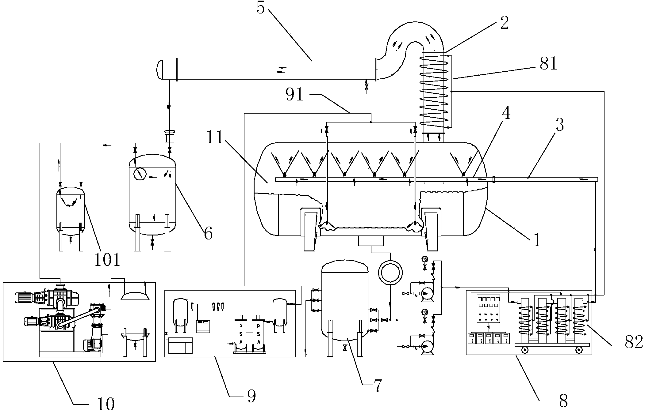
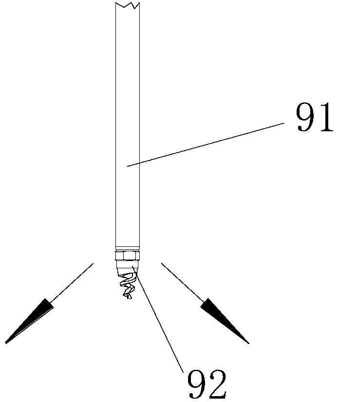
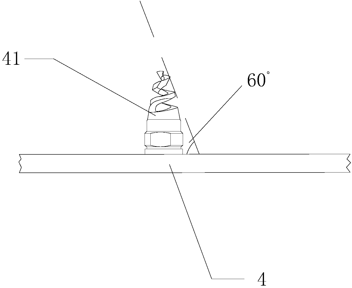
[0026] Such as figure 1 , figure 2 , image 3 , Figure 4 As shown, a waste mineral oil distillation equipment includes: a reaction kettle 1, a distillation tower 2, an external oil delivery pipeline 3, an oil injection pipeline 4, a condenser 5, an oil collection tank 6, a refueling tank 7, a heating unit 8, Nitrogen generating unit 9, vacuum unit 10, distillation tower 2 is set above the reaction kettle 1 and connected to the condenser 5, one end of the oil c...


PUM


Abstract

The invention provides waste mineral oil distilling equipment, which comprises a reaction kettle, a distilling tower, an external oil-conveying pipeline, an oil-jetting pipeline, a condenser, an oil collecting tank, an oil filling tank, a heating unit, a nitrogen making unit and a vacuum unit, wherein the distilling tower is arranged above the reaction kettle, and is connected with the condenser; one end of the oil collecting tank is connected with the condenser through a pipeline, and the other end of the oil collecting tank is connected with the vacuum unit through a pipeline; one end of the external oil-conveying pipeline is connected with the oil filling tank, and the other end of the external oil-conveying pipeline is connected with the oil-jetting pipeline positioned inside the reaction kettle; the heating unit is used for supplying heat energy to the distilling tower and the external oil-conveying pipeline; the nitrogen making unit extends into a nitrogen filling pipe inside the reaction kettle, and is used for conveying nitrogen into the reaction kettle. Under the pulling action of the vacuum unit and the pushing and stirring actions of the nitrogen making unit, the output and the yield of a finished product can be increased, and the cost is lowered.

Description

technical field [0001] The invention relates to the field of oil refining, in particular to waste mineral oil distillation equipment. Background technique [0002] Since mineral oil and the like are non-renewable resources, and, in the process of use, the waste of oil products, the global energy crisis, etc., the regeneration and extraction of waste mineral oil has become more and more important. The traditional waste mineral oil distillation In the refining equipment, due to the constraints of the equipment structure, such as the inaccurate temperature control of the heating equipment, the segmental control during the refining process is not accurate, and because the oil and gas will be subjected to many resistances during the movement process, the temperature will drop, and then flow back. To prevent this phenomenon, the traditional method is to add some insulation materials to the outer wall of the distillation tower, but the effect of this is not ideal. In the traditiona...

Claims


Application Information

Patent Timeline
IPC IPC(8): C10G7/00
Inventor 刘展鸿
Owner 佛山市和挚承环保科技有限公司
Learn More