Electric control device of engine extinguisher and control method of engine extinguisher

A technology of electronic control device and flame extinguisher, which is applied in the direction of engine control, machine/engine, mechanical equipment, etc. It can solve the problems of motor overshoot, no electrical signal acquisition, device burnout, etc., to improve reliability and avoid contact Sticking, the effect of reducing the motor speed

Active Publication Date: 2014-04-30
KEBODA TECH CO LTD +2
View PDF7 Cites 2 Cited by
  • Summary
  • Abstract
  • Description
  • Claims
  • Application Information

AI Technical Summary

Problems solved by technology

[0003] 1. Without any feedback compensation measures, when a fault occurs, no measures can be taken for the fault
After overcurrent occurs, the power supply can only be cut off by the power fuse, which is prone to burn out of components and even wiring harnesses;
[0004] 2. Relays are generally used as the motor drive circuit, without collecting any electrical signals, and only have the output drive function;
[0005] 3. The micro switch is used as the driving current loop. When the switch handle is switched, the contacts are very prone to sticking, resulting in product failure or even device burnout;
[0006] 4. The motor is easy to overshoot, resulting in a stroke out of tolerance

Method used


Image

  • Electric control device of engine extinguisher and control method of engine extinguisher
  • Electric control device of engine extinguisher and control method of engine extinguisher
  • Electric control device of engine extinguisher and control method of engine extinguisher

Examples


Embodiment Construction

[0023] The present invention will be further described below in conjunction with the accompanying drawings.

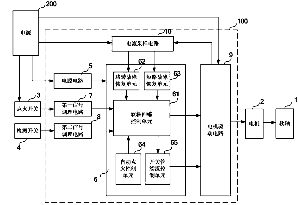
[0024] Please refer to figure 1 . The engine flame extinguisher includes a flexible shaft 1, a motor 2 for driving the flexible shaft 1 to extend and retract, a detection switch 4 and an electric control device 100 that are turned on and off triggered by the extension and retraction of the flexible shaft. The vehicle body power supply 200 supplies power to the engine flame extinguisher. According to an embodiment of the present invention, the electronic control device 100 of a flame extinguisher includes a power supply circuit 5, a main controller 6, a first signal conditioning circuit 7, a second signal conditioning circuit 8, and a motor drive capable of driving the motor 2 forward and reverse. The circuit 9 and the current sampling circuit 10 for collecting the driving current of the motor. The vehicle body power supply 200 supplies power to the ignition switch 3...


PUM


Abstract

The invention discloses an electric control device of an engine extinguisher. The engine extinguisher comprises a flexible shaft, a motor used for driving the flexible shaft to stretch out and retract back and a detection switch which is turned on or turned off through triggering of the stretching operation and the retraction operation of the flexible shaft. The electric control device comprises a power circuit, a main controller, a first signal processing circuit, a second signal processing circuit, a motor driving circuit and a current sampling circuit used for sampling a driving current of the motor. The input end of the first signal processing circuit is connected with the signal output end of an ignition switch. The input end of the second signal processing circuit is connected with the signal output end of the detection switch. The input end of the main controller is respectively connected with the output end of the first signal processing circuit, the output end of the second signal processing circuit and the output end of the current sampling circuit and the output end of the main controller is connected with the input end of the motor driving circuit. The invention further discloses a control method of the engine extinguisher. According to the electric control device of the engine extinguisher and the control method of the engine extinguisher, the current overcurrent protection function and the self-recovery function when the current is abnormal are achieved and in addition, a motor driving current does not flow across the detection switch.

Description

technical field [0001] The invention relates to an electronic control device of an engine flame extinguisher and a control method thereof. Background technique [0002] Construction machinery diesel engine oil circuit on-off device, commonly known as "flame extinguisher". A kind of flame extinguisher commonly used at present is electric control cable type, mainly is made up of electronic control device, gear reduction mechanism, mechanical transmission mechanism, micro switch, flexible shaft and flexible shaft drive motor etc. The main disadvantages of existing electronically controlled cable-type flame extinguishers are as follows: [0003] 1. Without any feedback compensation measures, when a fault occurs, no measures can be taken for the fault. After overcurrent occurs, the power supply can only be cut off by the power fuse, which is prone to burn out of components and even wiring harnesses; [0004] 2. Relays are generally used as the motor drive circuit, without coll...

Claims


Application Information

Patent Timeline
Patent Type & Authority Applications(China)
IPC IPC(8): F02D11/10
Inventor 唐杰李凌耀
Owner KEBODA TECH CO LTD
Why Eureka
Try Eureka