Sucker and sucking method thereof

A suction cup and suction cup base technology, applied in suction cups, connecting components, mechanical equipment, etc., can solve the problems of easy installation by consumers, the suction cup cannot work effectively, the installation procedure is complicated, etc. Humanized effect

Inactive Publication Date: 2014-04-30
TECMAGIC TECHMOLOGIES JIANGYIN CO LTD
View PDF9 Cites 8 Cited by
  • Summary
  • Abstract
  • Description
  • Claims
  • Application Information

AI Technical Summary

Problems solved by technology

However, these technologies also have insufficient adsorption to a certain extent; they cannot be used on rough surfaces; they are inconvenient to install and cannot be installed with one hand; the installation procedure is complicated, and consumers are easy to install them incorrectly;

Method used


Image

  • Sucker and sucking method thereof
  • Sucker and sucking method thereof
  • Sucker and sucking method thereof

Examples


Embodiment 1

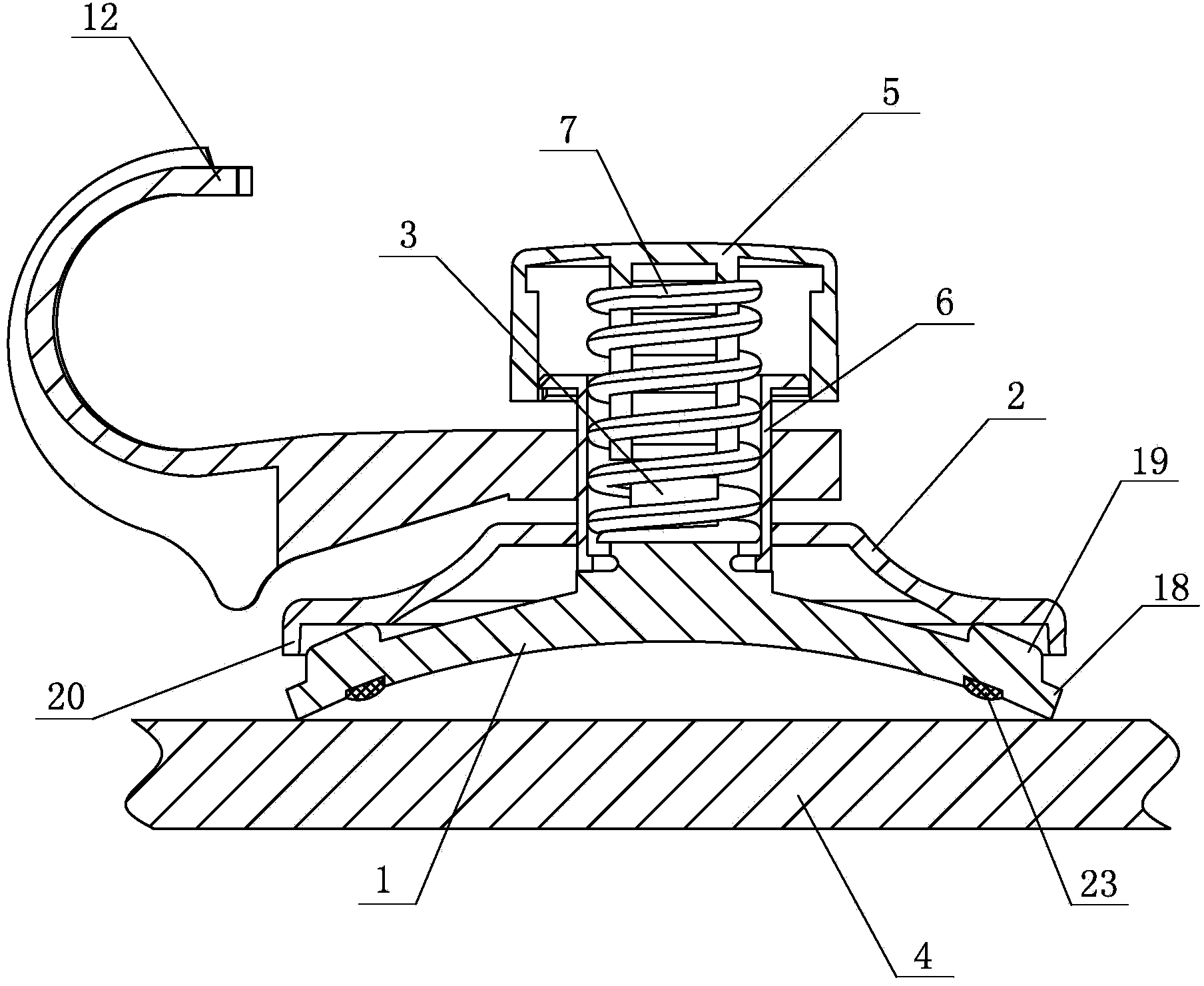
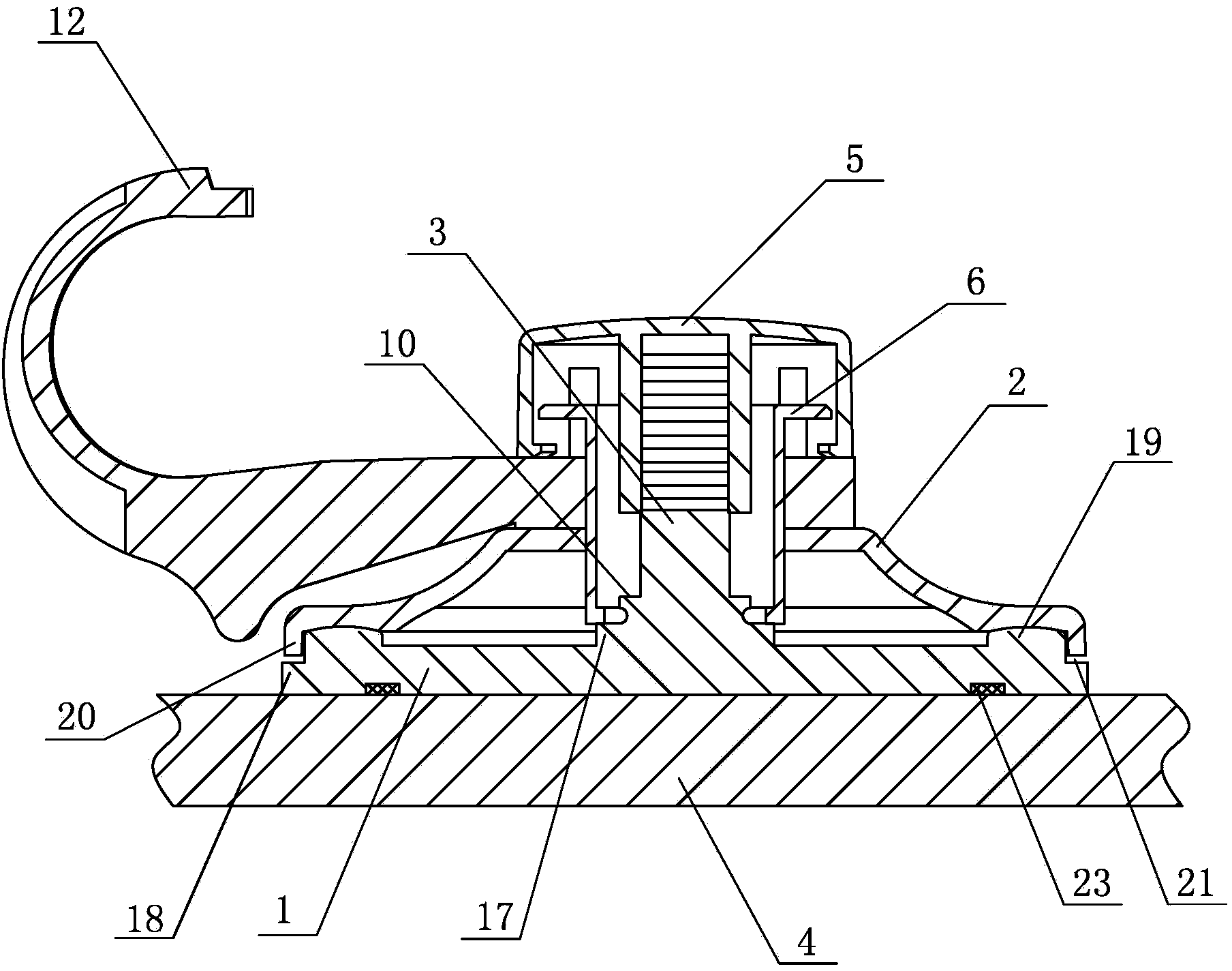
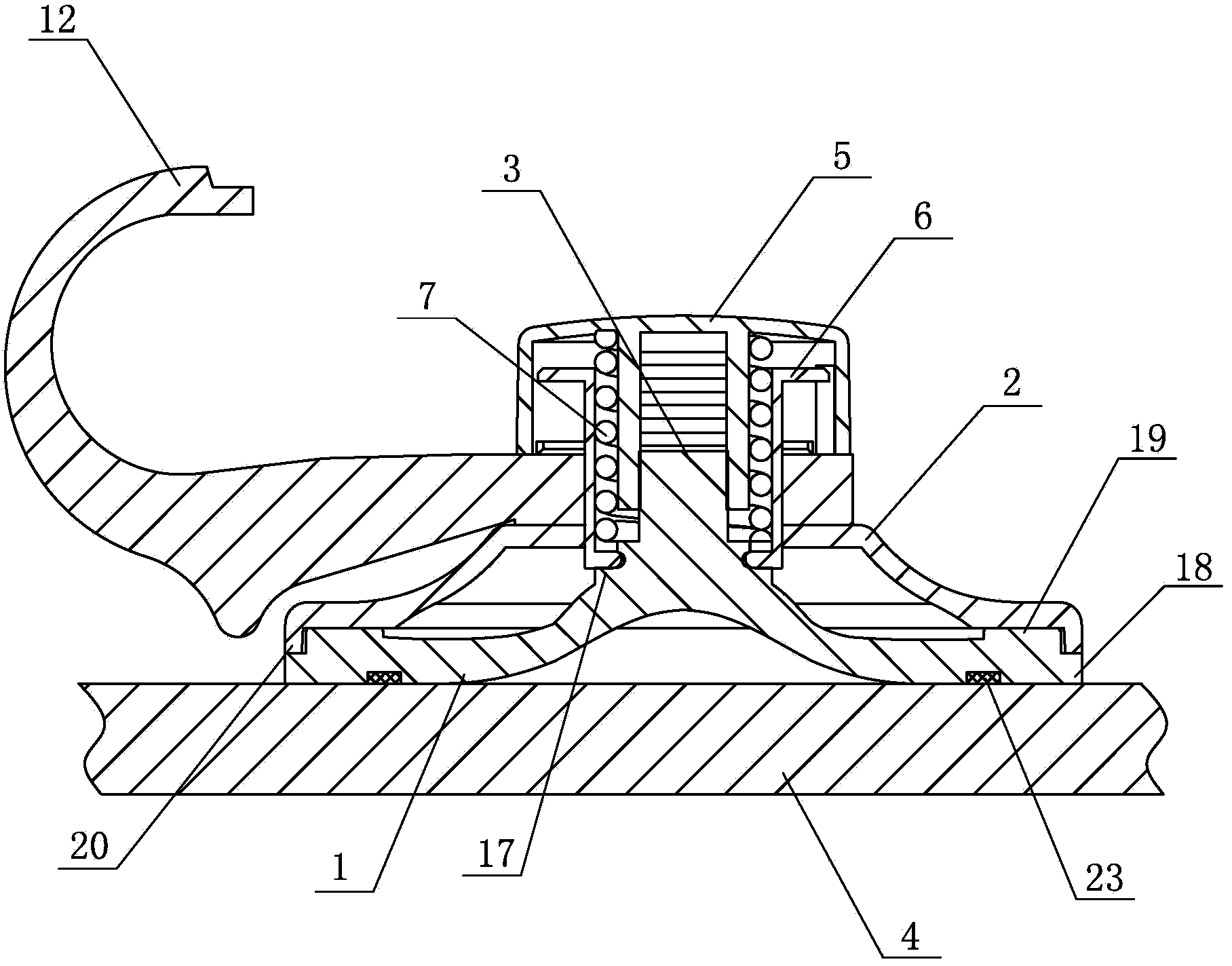
[0055] see Figure 1-10 As shown, the structure of the suction cup is as follows: a suction cup, including a suction cup base 1 made of elastic material, a suction cup cover 2 and an elastic pressing member arranged on the back of the suction cup base 1, and the suction cup cover 2 is not rigid. Deformed cover plate; the elastic pressing part is connected with the suction cup base 1 through the central connecting part 3, and the opening of the suction cup base 1 is a concave cavity facing the fixed surface 4, and the elastic pressing part is connected with the center The parts 3 are threaded, and the elastic pressing part can be rotated to lift the central connecting part 3 and then the suction cup base 1 .

[0056] Between the central connecting piece 3 and the sealing edge 18 on the edge of the suction cup base 1, an annular protrusion 19 corresponding to the pressing part of the edge of the suction cup cover plate 2 is arranged on the back of the suction cup base 1, the ann...

Embodiment 2

[0077]In this embodiment, the suction cup base is a flat surface suction cup base. Since the product is often assembled when it is sold, the suction cup base will have a certain indentation, or a certain indentation will occur due to a consumer's misuse, thus affecting Correctly installed, the structure of the present invention can avoid the occurrence of the above-mentioned unfavorable conditions. Other structures and usage methods of the suction cup are similar to those in Embodiment 1 and will not be repeated here.

Embodiment 3

[0079] In this embodiment, the suction cup cover is an elastic cover, and this elastic cover has a certain strength. Therefore, when the elastic pressing member is rotated, the elastic cover will also be deformed to a certain extent, thereby giving the suction cup base a certain degree of deformation. The edges apply extra elastic pressure to facilitate adsorption.


PUM


Abstract

The invention discloses a sucker. The sucker comprises a sucker base made of an elastic material, a sucker cover plate and an elastic pressing part. The sucker cover plate and the elastic pressing part are arranged on the back of the sucker base. The sucker is characterized in that the elastic pressing part comprises an outer cover, an inner cover and a spring, the spring is arranged between the outer cover and the inner cover, a sleeve is arranged inside the outer cover, the sleeve can penetrate the spring and the inner cover to be in threaded connection with a center connecting piece, the outer cover and the inner cover are movably connected, and the bottom of the center connecting piece is connected with the bottom of the inner cover. Mounting error of a consumer can be effectively avoided, firmness and durability of the sucker are improved, and the sucker is human friendly and reusable.

Description

technical field [0001] The invention relates to a suction cup, in particular to a suction cup with high adsorption force, durability and wide application range and an adsorption method thereof. Background technique [0002] Vacuum suction cup is a technology that maintains the attachment of two objects through vacuum. The chassis of vacuum suction cups is generally made of soft elastic materials. The chassis of vacuum suction cups is generally placed on a fixed surface, and then the chassis is cleaned. Press to make the bottom surface of the chassis adhere to the fixed surface, so that the air between the chassis and the fixed surface is squeezed out. When the pressing pressure decreases, the chassis rebounds through its own elasticity to form a vacuum chamber, and the suction cup is fixed on the fixed surface by internal and external negative pressure. [0003] In the prior art, as disclosed in the Chinese patent "Air Suction Base for Suction Support Device and Its Accesso...

Claims


Application Information

Patent Timeline
Patent Type & Authority Applications(China)
IPC IPC(8): F16B47/00
Inventor 帕特里克·施密特刘如意刘元喜
Owner TECMAGIC TECHMOLOGIES JIANGYIN CO LTD
Why Eureka
Try Eureka