Supercharge Your Innovation With Domain-Expert AI Agents!

Dynamic balance-adjustable transmission shaft structure and machining method for same

A transmission shaft and balancing technology, applied in the directions of shafts, shafts and bearings, mechanical equipment, etc., can solve the problems of small bonding force, inability to achieve dynamic balance of the physical transmission shaft 21, and reducing the electrical conductivity and thermal conductivity of the physical transmission shaft 21.

Inactive Publication Date: 2014-04-30
SHANGHAI GKN DRIVE SYST
View PDF6 Cites 1 Cited by
  • Summary
  • Abstract
  • Description
  • Claims
  • Application Information

AI Technical Summary

Problems solved by technology

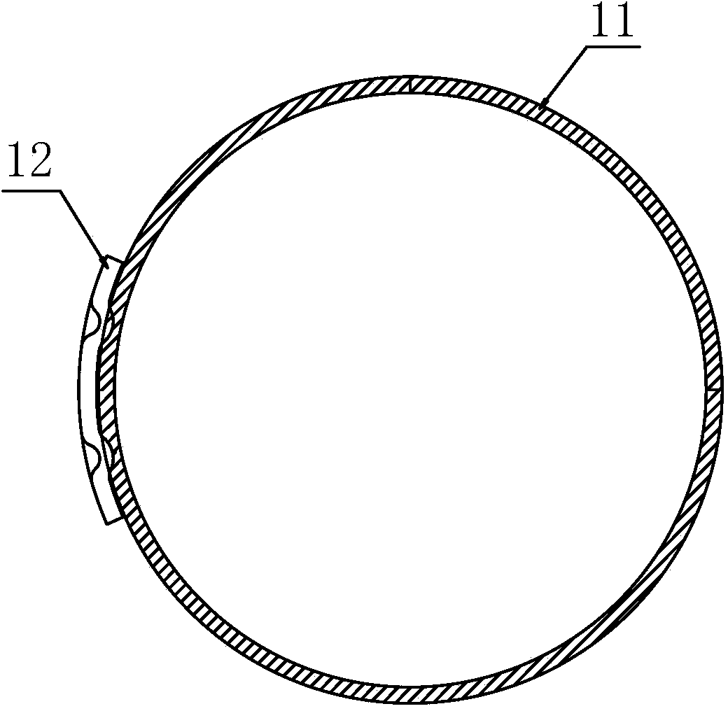
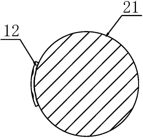
[0005] like figure 1 and figure 2 As shown, the vehicle transmission system usually adopts the tubular transmission shaft 11. However, sometimes the vehicle transmission system cannot choose the tubular transmission shaft 11 due to space limitations and strength requirements, and can only choose the solid transmission shaft 21.
Since the physical transmission shaft 21 is a solid body, the electrical conductivity and thermal conductivity of the physical transmission shaft 21 are reduced, causing the electrical conductivity and thermal conductivity of the physical transmission shaft 21 to fail to meet the electrical conductivity and thermal conductivity requirements of resistance projection welding.
When the dynamic balance plate 12 is connected with the physical transmission shaft 21 by resistance projection welding, the bonding force between the dynamic balance plate 12 and the physical transmission shaft 21 is relatively small, and the dynamic balance plate 12 is easy to break away from the physical transmission shaft 21 , the dynamic balance of the solid transmission shaft 21 cannot be realized

Method used


Image

  • Dynamic balance-adjustable transmission shaft structure and machining method for same
  • Dynamic balance-adjustable transmission shaft structure and machining method for same
  • Dynamic balance-adjustable transmission shaft structure and machining method for same

Examples


Embodiment Construction

[0031] The implementation of the present invention will be illustrated by specific specific examples below, and those skilled in the art can easily understand other advantages and effects of the present invention from the contents disclosed in this specification.

[0032] It should be noted that the structures, proportions, sizes, etc. shown in the drawings attached to this specification are only used to match the content disclosed in the specification, for those who are familiar with this technology to understand and read, and are not used to limit the implementation of the present invention. Limiting conditions, so there is no technical substantive meaning, any modification of structure, change of proportional relationship or adjustment of size, without affecting the effect and purpose of the present invention, should still fall within the scope of the present invention. within the scope covered by the disclosed technical content. At the same time, terms such as "upper", "lo...


PUM


Abstract

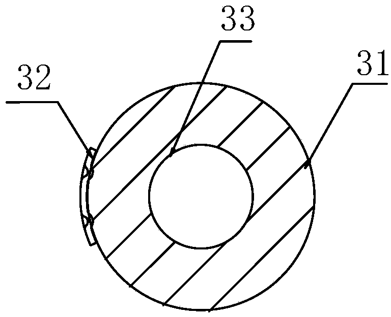
The invention provides a dynamic balance-adjustable transmission shaft structure which comprises a solid transmission shaft, wherein an axial through hole is formed in the solid transmission shaft; the diameter of the axial through hole does not exceed 1 / 2 of the external diameter of the solid transmission shaft; a dynamic balance piece is welded on the outer circumferential wall of the solid transmission shaft in a resistance projection welding way. According to the dynamic balance-adjustable transmission shaft structure, the electrical conductivity and thermal conductivity of the solid transmission shaft can be greatly improved to meet the requirements of the resistance projection welding on the electrical conductivity and thermal conductivity of a material through the axial through hole; the dynamic balance piece can be firmly welded with the solid transmission shaft together in the resistance projection welding way, so that the dynamic balance of the solid transmission shaft is realized, and the service life is prolonged. The invention further provides a method for machining the dynamic balance-adjustable transmission shaft structure. The dynamic balance-adjustable transmission shaft structure machined by the method has the advantage of firmer combination of the dynamic balance piece and the solid transmission shaft.

Description

technical field [0001] The invention relates to a solid transmission shaft, in particular to an adjustable and balanced transmission shaft structure and a processing method thereof. Background technique [0002] The transmission shaft of the automobile can transmit torque between two shafts with different shaft centers or even between two shafts whose relative positions are constantly changing during the working process. The circular object parts that can be moved or rotated by connecting or assembling various accessories are generally used light and durable. Made of alloy steel pipe with good torsion resistance. The function of the transmission shaft of the car is to transmit torque between two shafts with different shaft centers or even two shafts whose relative positions are constantly changing during the working process. [0003] The automobile transmission shaft is composed of a shaft tube, a telescopic sleeve and a universal joint. The telescopic sleeve can automatic...

Claims


Application Information

Patent Timeline
IPC IPC(8): F16C3/02
Inventor 陈黎琪
Owner SHANGHAI GKN DRIVE SYST
Features
  • R&D
  • Intellectual Property
  • Life Sciences
  • Materials
  • Tech Scout
  • Unparalleled Data Quality
  • Higher Quality Content
  • 60% Fewer Hallucinations
Learn More