
One-way rotating crank mechanism

A technology of slewing mechanism and crank, which is applied in the field of one-way slewing mechanism of crank, can solve the problems such as inability to realize unidirectional movement, and achieve the effect of simple structure and easy operation

Inactive Publication Date: 2014-04-30
CHONGQING MING SHIELD ELECTROMAGNETIC VALVE
View PDF0 Cites 4 Cited by
  • Summary
  • Abstract
  • Description
  • Claims
  • Application Information

AI Technical Summary

Problems solved by technology

[0003] The present invention intends to provide a crank one-way rotary mechanism to solve the problem that the rotary motion mechanism of the machine tool in the prior art cannot realize one-way motion

Method used


Image

  • One-way rotating crank mechanism

Examples


Embodiment Construction

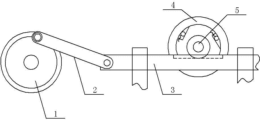
[0009] according to figure 1 As shown, the crank one-way rotary mechanism in the embodiment of the present invention includes a frame, a driving wheel 1 arranged on the frame, a driven shaft 5 slidingly connected with the frame, and a driven wheel 4 fixed to the driven shaft 5 , also includes a crank 2 and a gear connected to the driven shaft 5 through a one-way bearing, a plurality of hinge holes are arranged on the crank 2, one end of the crank 2 is hinged to the rim of the driving wheel, and the other end of the crank 2 is hinged to an axially movable slide Rod 3, the two ends of the sliding rod 3 are slidingly connected with the frame, the middle part of the sliding rod 3 is provided with a section of rack, the rack is meshed with the gear, and the sliding connection between the frame and the sliding rod 3 is provided with a wear-resistant rubber sleeve.

[0010] What is described above is only an embodiment of the present invention, and common knowledge such as specific s...


PUM


Abstract

The invention discloses a one-way rotating crank mechanism, and aims at solving the problem that a machine tool rotary motion mechanism in the prior art is incapable of realizing one-way motion. The one-way rotating crank mechanism comprises a frame, a driving wheel arranged on the frame, a driven shaft slidingly connected with the frame and a driven wheel fixed with the driven shaft, and also a crank and a gear connected with the driven shaft through a one-way bearing, wherein a plurality of hinging holes are formed in the crank, one end of the crank is hinged to the rim of the driving wheel, while the other end of the crank is hinged to an axially movable sliding rod, the two ends of the sliding rod are slidingly connected with the frame, a section of rack is arranged on the middle part of the sliding rod, and the rack is engaged with the gear. The one-way rotating crank mechanism is simple in structure and high in practicability.

Description

technical field [0001] The invention relates to the technical field of machine tool processing, in particular to a crank one-way rotation mechanism. Background technique [0002] The rotary motion mechanism is commonly used in the rotary table of the machine tool, and the slotted wheel mechanism is more commonly used in the rotary motion mechanism. However, in actual use, the slotted wheel mechanism still has some shortcomings. The stroke cannot be adjusted, and the rotation angle cannot be too small to realize One-way movement, the acceleration of the sheave when it starts and stops is large, and there is an impact, and it will intensify with the increase of the speed or the decrease of the number of grooves of the sheave, so it is not suitable for high-speed movement. Angular movement. Contents of the invention [0003] The present invention intends to provide a crank one-way rotary mechanism to solve the problem that the rotary motion mechanism of a machine tool in the...

Claims


Application Information

Patent Timeline
Patent Type & Authority Applications(China)
IPC IPC(8): F16H37/12
CPCF16H37/12B23Q5/34
Inventor 姜静慧
Owner CHONGQING MING SHIELD ELECTROMAGNETIC VALVE
Features
  • Generate Ideas
  • Intellectual Property
  • Life Sciences
  • Materials
  • Tech Scout
  • Unparalleled Data Quality
  • Higher Quality Content
  • 60% Fewer Hallucinations
Learn More