butterfly valve

A butterfly valve and valve body technology, which is applied in the direction of lift valves, valve devices, engine components, etc., can solve the problems of large size and specification of butterfly valves, corrosive medium, and laborious opening of butterfly valves, so as to improve dustproof performance and corrosion resistance Ability to improve the effect of sealing performance

Active Publication Date: 2015-12-02
NINGBO TIANJILONG INTELLIGENT CONTROL TECH
View PDF5 Cites 1 Cited by
  • Summary
  • Abstract
  • Description
  • Claims
  • Application Information

AI Technical Summary

Problems solved by technology

However, the working environment of butterfly valves is mostly harsh, such as dusty, high temperature, high pressure of the circulating medium, corrosive medium, etc., and the size of the butterfly valve is getting larger and larger, so it is extremely laborious to open the butterfly valve

Method used


Image

  • butterfly valve
  • butterfly valve
  • butterfly valve

Examples


Embodiment Construction

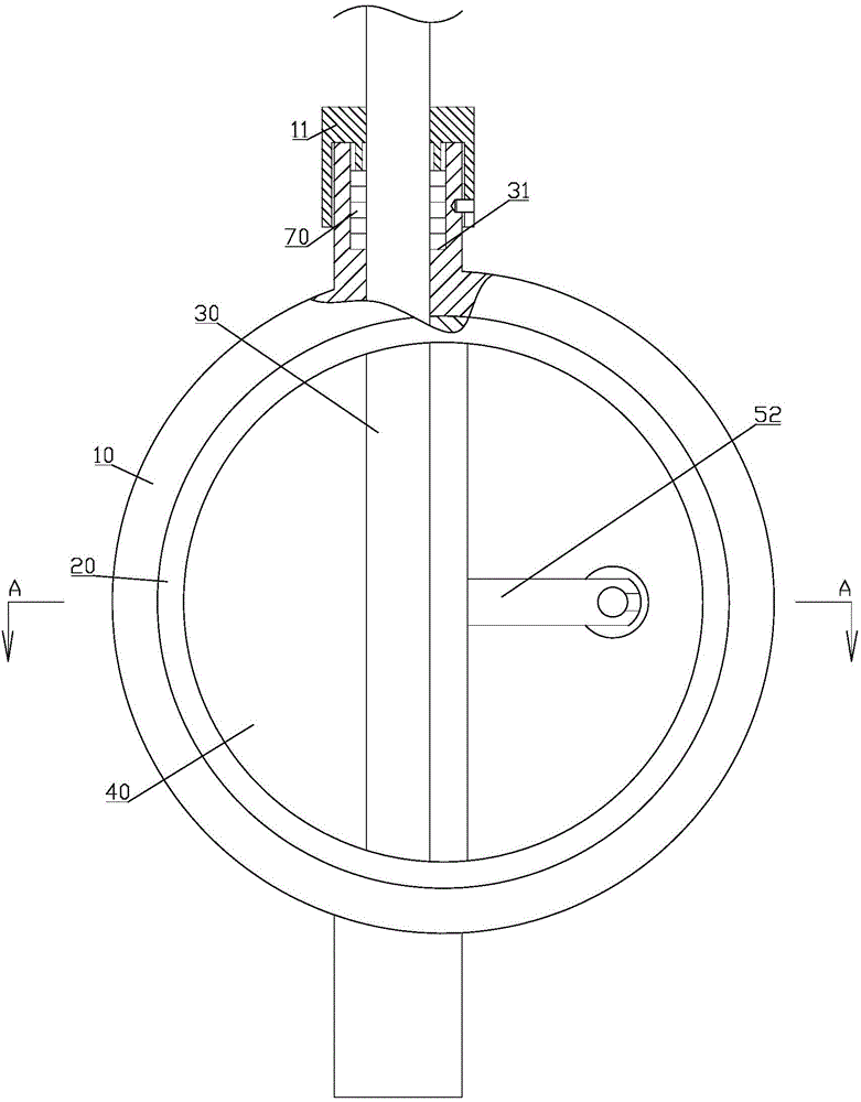
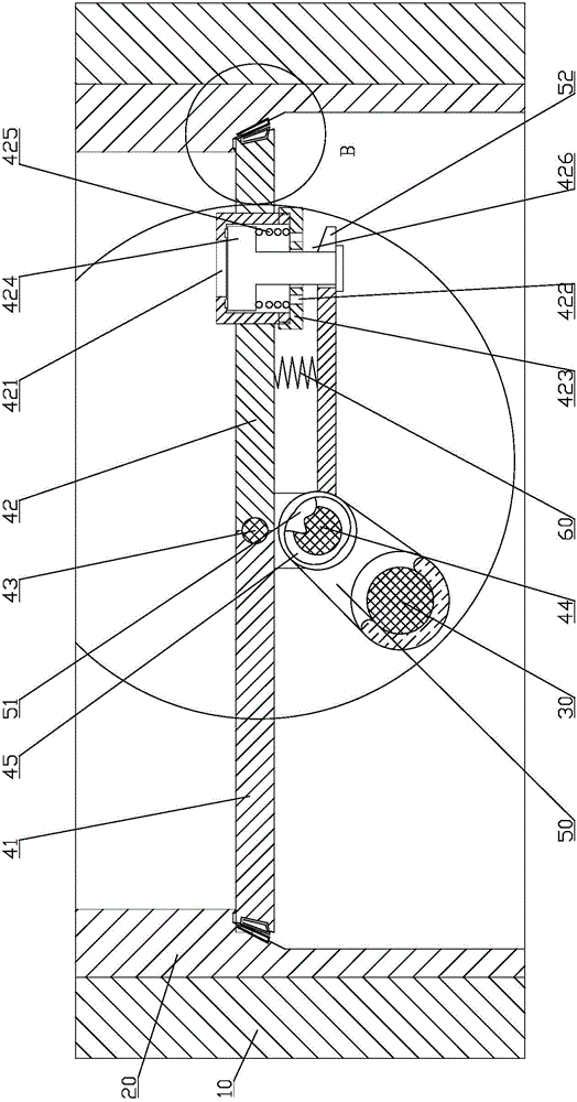
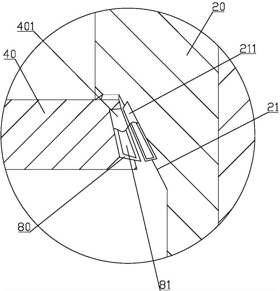
[0018] Examples, see Figure 1 to Figure 3 Shown: a butterfly valve, including a valve body 10, a valve seat 20, a valve stem 30, and a valve disc 40. specific:

[0019] The valve flap 40 includes a left flap body 41 and a right flap body 42 which are both semicircular, and the straight sides of the left flap body 41 and the right flap body 42 are hinged together by a hinge shaft 43 . That is, the left petal body 41 and the right petal body 42 are hinged together to form a complete circular valve flap 40 . The right petal body 42 is provided with a pressure relief hole 421 , and the pressure relief hole 421 is screwed with a cover 423 with a water permeable hole 422 on the side. The pressure relief hole 421 is provided with a sealing plug 424 , the upper part of the sealing plug 424 is provided with an annular groove 426 after passing through the cover 423 , and a compression spring 425 is provided between the middle part of the sealing plug 424 and the cover 423 . Apparent...


PUM


Abstract

The invention discloses a butterfly valve. The butterfly valve comprises a valve body, a valve base, a valve rod and a valve flap. According to the butterfly valve, the improvement is performed on the following performances: 1, the valve flap is divided into two parts, a pressure release hole is formed in the valve flap, so that the valve flap releases pressure before rotating wholly and opens in steps during opening, thus the butterfly valve is small in opening pressure and labor-saving; 2, due to the introduction of a titanium material and a fluorine plastic layer, so that the corrosion resistance of the butterfly valve is greatly improved; 3, due to the adoption of a dustproof ring, so that the dustproof performance of the butterfly valve is improved; and 4, due to the adoption of a sealing tape, the sealing performance of the butterfly valve is improved. Through the manner, the butterfly valve is excellent in comprehensive performance.

Description

technical field [0001] The invention relates to the technical field of valves, in particular to a butterfly valve. Background technique [0002] It is undeniable that butterfly valves have become one of the most widely used valves at present. Generally, a butterfly valve includes a valve body, a valve seat, a valve stem, and a valve disc. That is, the valve seat is fixed in the inner cavity of the valve, the valve disc is located in the inner cavity of the valve seat, and after the valve disc rotates, its edge and the valve seat are sealed or opened, and the valve rod is used to drive the valve disc to perform After rotating, the upper part of the valve stem passes through the upper part of the valve body and is connected to a rotating device such as a handle or an actuator. However, the working environment of butterfly valves is mostly harsh, such as dusty, high temperature, high pressure of the circulating medium, corrosive medium, etc., and the size of butterfly valves ...

Claims


Application Information

Patent Timeline
Patent Type & Authority Patents(China)
IPC IPC(8): F16K1/226F16K1/36F16K1/32
CPCF16K1/222F16K1/2261F16K1/2268
Inventor 孙得浩易松达李洪峰王昌林
Owner NINGBO TIANJILONG INTELLIGENT CONTROL TECH
Why Eureka
Try Eureka