
Backlight and display device

A technology of backlight and light source, which is applied in the direction of electric light source, lighting device, light source fixation, etc. It can solve the problems of increasing the number of light sources, large power consumption of display devices, etc., and achieve uniform overall brightness, uniform display brightness, and overall The effect of thickness reduction

Inactive Publication Date: 2014-04-30
BEIJING BOE DISPLAY TECH CO LTD +1
View PDF6 Cites 10 Cited by
  • Summary
  • Abstract
  • Description
  • Claims
  • Application Information

AI Technical Summary

Problems solved by technology

In order to fully mix the light emitted by the light source 2 and irradiate the display panel more uniformly, a certain light mixing distance is generally maintained between the diffuser plate 7 and the back plate 1, and the light mixing distance makes the thickness of the direct-type backlight become smaller. It is very large, which is not conducive to the thinning of the display device
In addition, since the direct type backlight uses a large number of light sources, the power consumption will be relatively large.
[0004] For large-size (greater than 60 inches) display devices, as the size of the display panel increases, the light mixing distance between the diffuser plate 7 and the back plate 1 also increases correspondingly, which is more detrimental to the thinness of the display device At the same time, the number of light sources will increase correspondingly, which makes the power consumption of the display device also become larger

Method used


Image

  • Backlight and display device
  • Backlight and display device
  • Backlight and display device

Examples


Embodiment 1

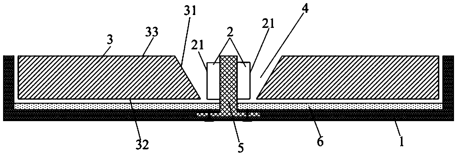
[0029] This embodiment provides a backlight, such as figure 2 As shown, it includes a backplane 1, a light source 2, and a light guide plate 3. The light guide plate 3 includes at least two pieces. The light guide plates 3 are spaced apart from each other and arranged on the same layer above the backplane 1. The light source 2 is arranged on two adjacent light guide plates 3. In the formed separation area 4 , the light emitting surface 21 of the light source 2 is opposite to the first side 31 of the light guide plate 3 facing the separation area 4 . Such setting reduces the distance between the far light end of the large-size light guide plate 3 and the light source 2, so that the far light end of the light guide plate 3 can also achieve the brightness required for display, and then the large-size light guide plate 3 The overall brightness is more uniform.

[0030] Wherein, the light emitting surface 21 of the light source 2 refers to the surface where the light emitted by t...

Embodiment 2

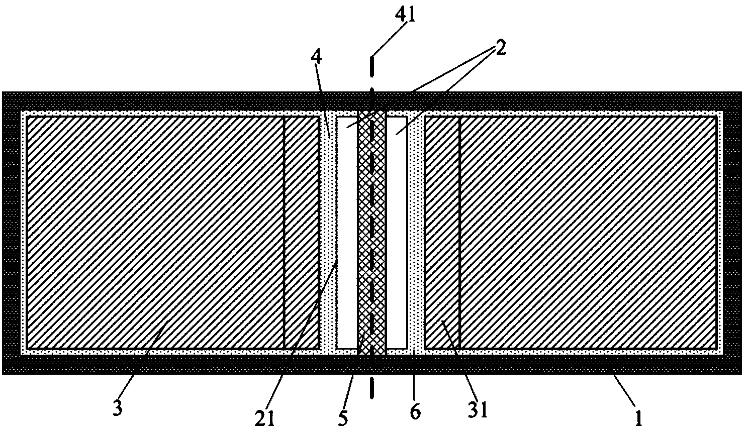
[0042] This embodiment provides a backlight source. The difference from Embodiment 1 is that Figure 4 As shown, there are four light guide plates 3 . The size and shape of the four light guide plates 3 are the same, and any two adjacent light guide plates 3 are symmetrically arranged with the center line 41 of the interval region 4 between the two light guide plates 3 as the axis of symmetry.

[0043] Other structures and materials of the backlight in this embodiment are the same as those in Embodiment 1, and will not be repeated here.

[0044] It should be noted that the above four light guide plates 3 can also be Figure 5 Set as shown. Wherein, the side of the light guide plate 3 close to the side wall of the backplane 1 can be inclined at a certain angle like the first side 31 , or can be perpendicular to the bottom surface of the backplane 1 . As long as the first side 31 of the light guide plate 3 facing the interval region 4 is an inclined side (for example, the ang...

Embodiment 3

[0047] This embodiment provides a display device, including the backlight in any one of Embodiments 1-2.

[0048] By adopting the above-mentioned backlight source in the display device, the display brightness is more uniform, thereby greatly improving the display effect. In addition, by adopting the above-mentioned backlight source, the display device is not only lighter and thinner, but also has lower display power consumption.


PUM


Abstract

The invention provides a backlight and a display device. The backlight comprises a back plate, light sources and light guide plates, at least two light guide plates are arranged on the same layer above the back plate together at intervals, the light sources are arranged in interval areas formed by the adjacent light guide plates, and the light emitting faces of the light sources are opposite to the first side faces, towards the interval areas, of the light guide plates. According to the backlight, two or more light guide plates are arranged, the light sources are arranged in the interval areas between the adjacent light guide plates, the far ends of the light guide plates of a large size can reach luminance needed in the display process, therefore, the overall luminance of the light guide plates is more even, and then the display luminance of a display panel of a large size is more even. In addition, compared with a direct-lighting backlight, the backlight is light, thin and lower in energy consumption.

Description

technical field [0001] The present invention relates to the field of display technology, in particular to a backlight source and a display device. Background technique [0002] A display device is mainly composed of a display panel and a backlight source. According to the relative arrangement positions of the display panel and the backlight source, common backlight sources are divided into direct-type and side-type. [0003] Such as figure 1 Shown is a direct type backlight, the light source 2 is arranged on the backplane 1, and the diffuser plate 7 is arranged above the light source 2, and the diffuser plate 7 is used to mix and diffuse the light emitted by the light source 2, so that the light can be mixed evenly before onto the display panel. In order to fully mix the light emitted by the light source 2 and irradiate the display panel more uniformly, a certain light mixing distance is generally maintained between the diffuser plate 7 and the back plate 1, and the light...

Claims


Application Information

Patent Timeline
Patent Type & Authority Applications(China)
IPC IPC(8): F21S8/00F21V8/00F21V19/00
CPCG02F1/133615G02F2201/46G02B6/0085G02B6/0078G02B6/0068G02B6/009
Inventor 朱昆鹏金雄郑辉
Owner BEIJING BOE DISPLAY TECH CO LTD
Learn More