Collimator parallel optical axis orientation included angle calibration device

A calibration device and collimator technology, which is applied in the field of optical collimation systems, can solve the problems of time-consuming and laborious operations, complex operations, and inability to adapt to collimator calibration, and achieve the effects of simple and convenient operation, high calibration accuracy, and reduced manufacturing difficulty and cost.

Active Publication Date: 2014-04-30
THE GENERAL DESIGNING INST OF HUBEI SPACE TECH ACAD
View PDF6 Cites 6 Cited by
  • Summary
  • Abstract
  • Description
  • Claims
  • Application Information

AI Technical Summary

Problems solved by technology

[0004] 1. Since both the autocollimating theodolite and the collimator need to be leveled before calibration, the operation is complicated and time-consuming;
[0005] 2. Since the calibration method requ

Method used


Image

  • Collimator parallel optical axis orientation included angle calibration device
  • Collimator parallel optical axis orientation included angle calibration device
  • Collimator parallel optical axis orientation included angle calibration device

Examples


Embodiment 1

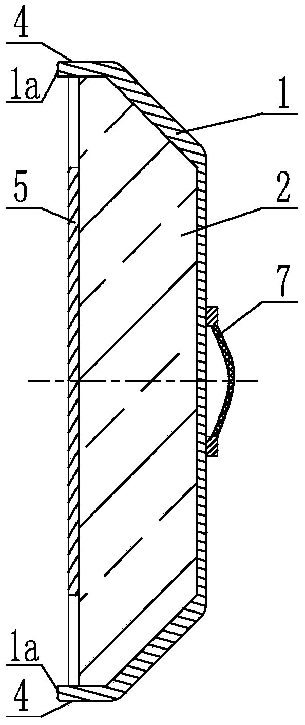
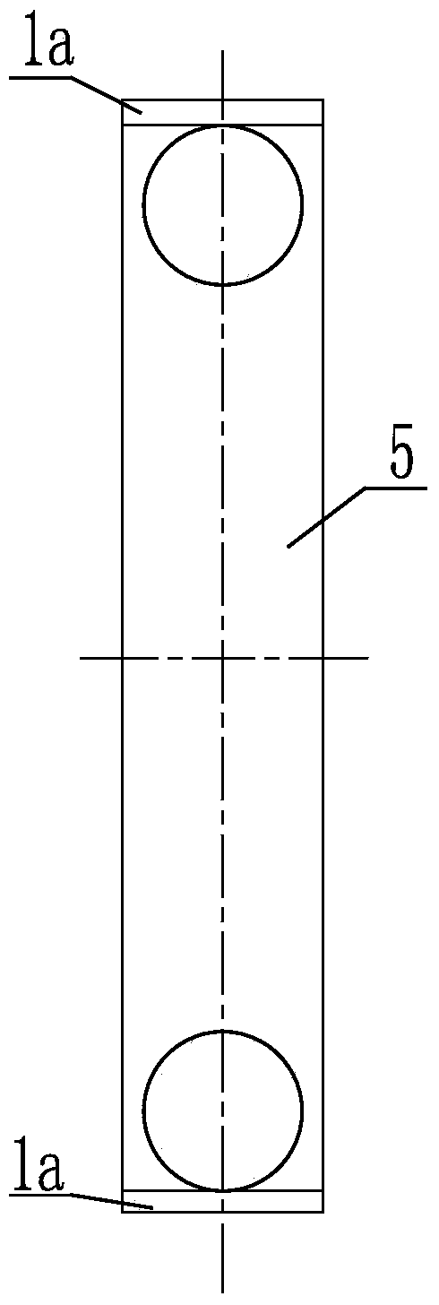
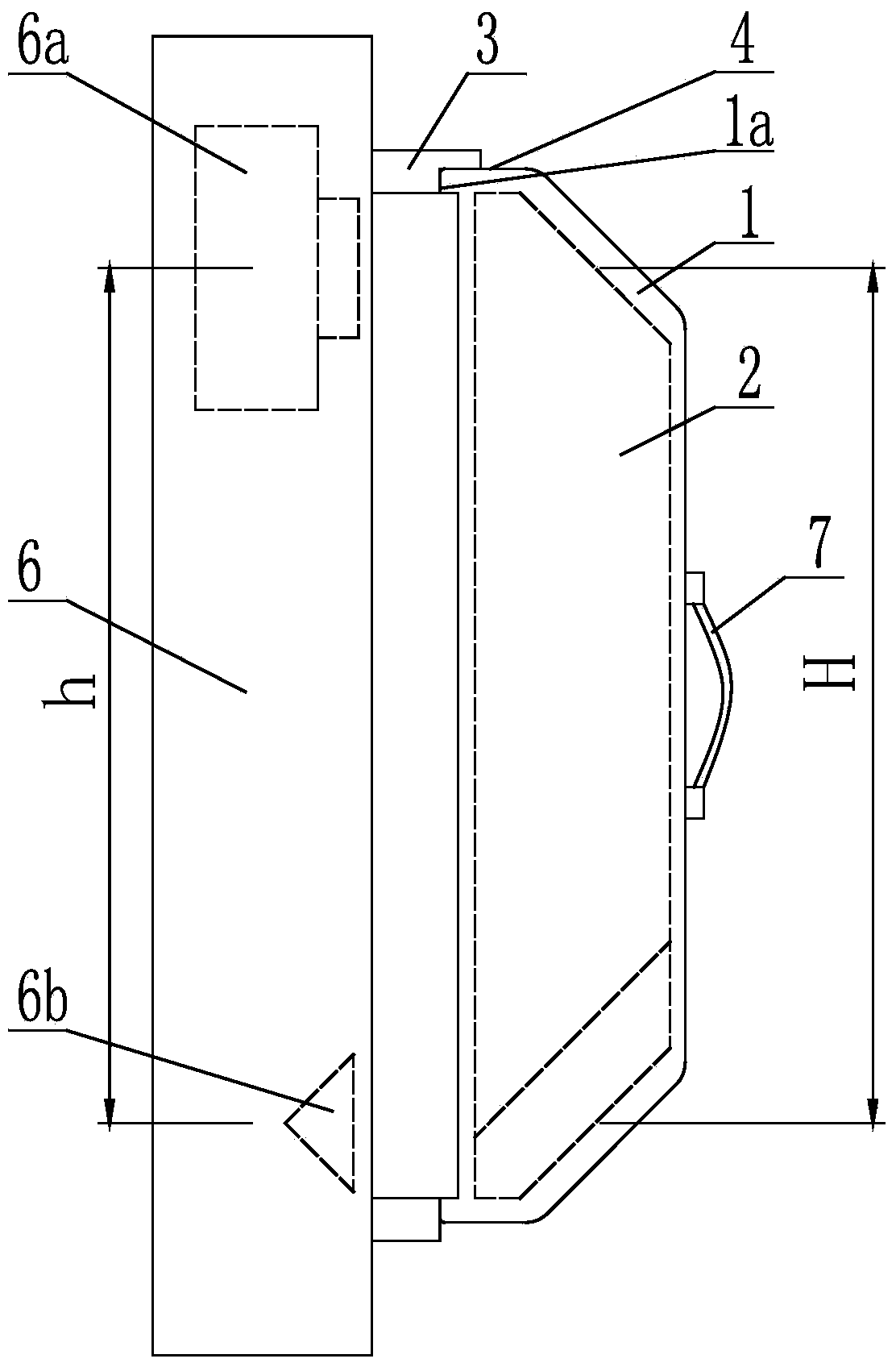
[0037] Embodiment 1: as figure 1 The shown azimuth angle calibration device parallel to the optical axis of the collimator includes a base 1 and a calibration prism 2 installed in the base 1, and the calibration prism 2 is used for a measurement of the collimator 6 to be calibrated. The collimated light of the head 6a is guided in parallel and reverse to the CCD sensor of another measuring head 6a of the collimator 6 to be calibrated or at the optical axis of the rectangular prism 6b of the collimator 6 to be calibrated. Including rectangular roof prism DⅡj-1802a. By using the calibration prism 2, the collimated light of a measuring head 6a of the collimator 6 to be calibrated is guided in parallel and reverse to the CCD sensor of the other measuring head 6a of the collimator 6 to be calibrated or the collimator to be calibrated The technical scheme at the optical axis of the rectangular prism 6b of the instrument 6 can easily measure the azimuth included angle of the collima...

Embodiment 2

[0042] Embodiment 2: as figure 1 The shown azimuth angle calibration device parallel to the optical axis of the collimator includes a base 1 and a calibration prism 2 installed in the base 1, and the calibration prism 2 is used for a measurement of the collimator 6 to be calibrated. The collimated light of the head 6a is guided in parallel and reverse to the CCD sensor of another measuring head 6a of the collimator 6 to be calibrated or at the optical axis of the rectangular prism 6b of the collimator 6 to be calibrated. Including rectangular roof prism DⅡj-1802a. By using the calibration prism 2, the collimated light of a measuring head 6a of the collimator 6 to be calibrated is guided in parallel and reverse to the CCD sensor of the other measuring head 6a of the collimator 6 to be calibrated or the collimator to be calibrated The technical scheme at the optical axis of the rectangular prism 6b of the instrument 6 can easily measure the azimuth included angle of the collima...


PUM


Abstract

The invention discloses a collimator parallel optical axis orientation included angle calibration device. The collimator parallel optical axis orientation included angle calibration device comprises a base and a calibration prism arranged in the base, wherein the calibration prism is used for guiding the collimated light of a measurement head of a collimator to be calibrated to a CCD sensor of the other measurement head of the collimator to be calibrated or the optical axis of a right-angle prism of the collimator to be calibrated in parallel in the reverse direction. The calibration prism comprises a right-angle roof prism DIIj-180. Due to the adoption of the technical scheme that the calibration prism guides the collimated light of the measurement head of the collimator to be calibrated to the CCD sensor of the other measurement head of the collimator to be calibrated or the optical axis of the right-angle prism of the collimator to be calibrated in parallel in the reverse direction, the orientation included angle of the collimator to be calibrated can be conveniently measured, and the operation is simple; due to the fact that rotation of the right-angle roof prism DIIj-180 does not affect the parallelism between the incidence optical axis and the outgoing optical axis, the calibration device and the collimator to be calibrated do not need to be leveled, and work efficiency is improved. The collimator parallel optical axis orientation included angle calibration device is suitable for calibrating collimators.

Description

technical field [0001] The invention relates to the field of optical aiming systems, in particular to a device for calibrating included angles between parallel optical axes of a collimator. Background technique [0002] In the automatic optical aiming system, in order to realize the azimuth reference transfer, a collimator is usually used. There are two common basic units of the collimator: one is the measuring head (optical measuring head with CCD angle measurement function, the English full name of CCD is It is a combination of charge-coupled device (charge-coupled device in Chinese) and a right-angle prism (right-angle prism DⅡ-180); the other is a combination of two measuring heads. However, since the two optical axes of the basic unit (the optical axis of the measuring head refers to its collimating optical axis, and the optical axis of the right-angle prism refers to its normal line) are not absolutely parallel and there is an included angle in azimuth, the collimator ...

Claims


Application Information

Patent Timeline
IPC IPC(8): G01M11/02
Inventor 沈小龙李丽徐明升
Owner THE GENERAL DESIGNING INST OF HUBEI SPACE TECH ACAD
Why Eureka
Try Eureka