Detector array for spectral CT

A photoelectric detector and radiation detector technology, applied in medical and non-medical inspection fields, can solve problems such as low light collection efficiency, achieve high optical detection efficiency, improve light collection efficiency, and save costs

Active Publication Date: 2014-04-30
KONINKLIJKE PHILIPS ELECTRONICS NV
View PDF8 Cites 5 Cited by
  • Summary
  • Abstract
  • Description
  • Claims
  • Application Information

AI Technical Summary

Problems solved by technology

Because the light collection efficiency of a photodetector is directly proportional to the active area of ​​the photodetector, a 0.1 mm high active area of ​​the photodetector would produce an unduly low light collection efficiency

Method used


Image

  • Detector array for spectral CT
  • Detector array for spectral CT
  • Detector array for spectral CT

Examples


Embodiment Construction

[0022] see figure 1 , a computed tomography (CT) imaging device or CT scanner 10 includes a gantry 12 . The x-ray source 14 and source collimator 16 cooperate to produce a fan, cone, wedge, or other shaped x-ray beam directed into an examination region 18 containing an object such as a patient arranged on an object platform 20 (not shown). ). The object platform 20 moves linearly in the z-direction, while the x-ray source 14 on the rotating gantry 22 rotates about the z-axis.

[0023] Preferably, rotating gantry 22 rotates simultaneously with the linear advancement of object platform 20 , creating a generally helical trajectory of x-ray source 14 and collimator 16 around examination region 18 . However, other imaging modalities can also be used, such as single- or multi-slice imaging modalities, in which the gantry 22 rotates while the object platform 20 remains fixed, producing a generally circular trajectory of the x-ray source 14 on which axial images are acquired . Aft...


PUM

PropertyMeasurementUnit
thicknessaaaaaaaaaa
heightaaaaaaaaaa

Abstract

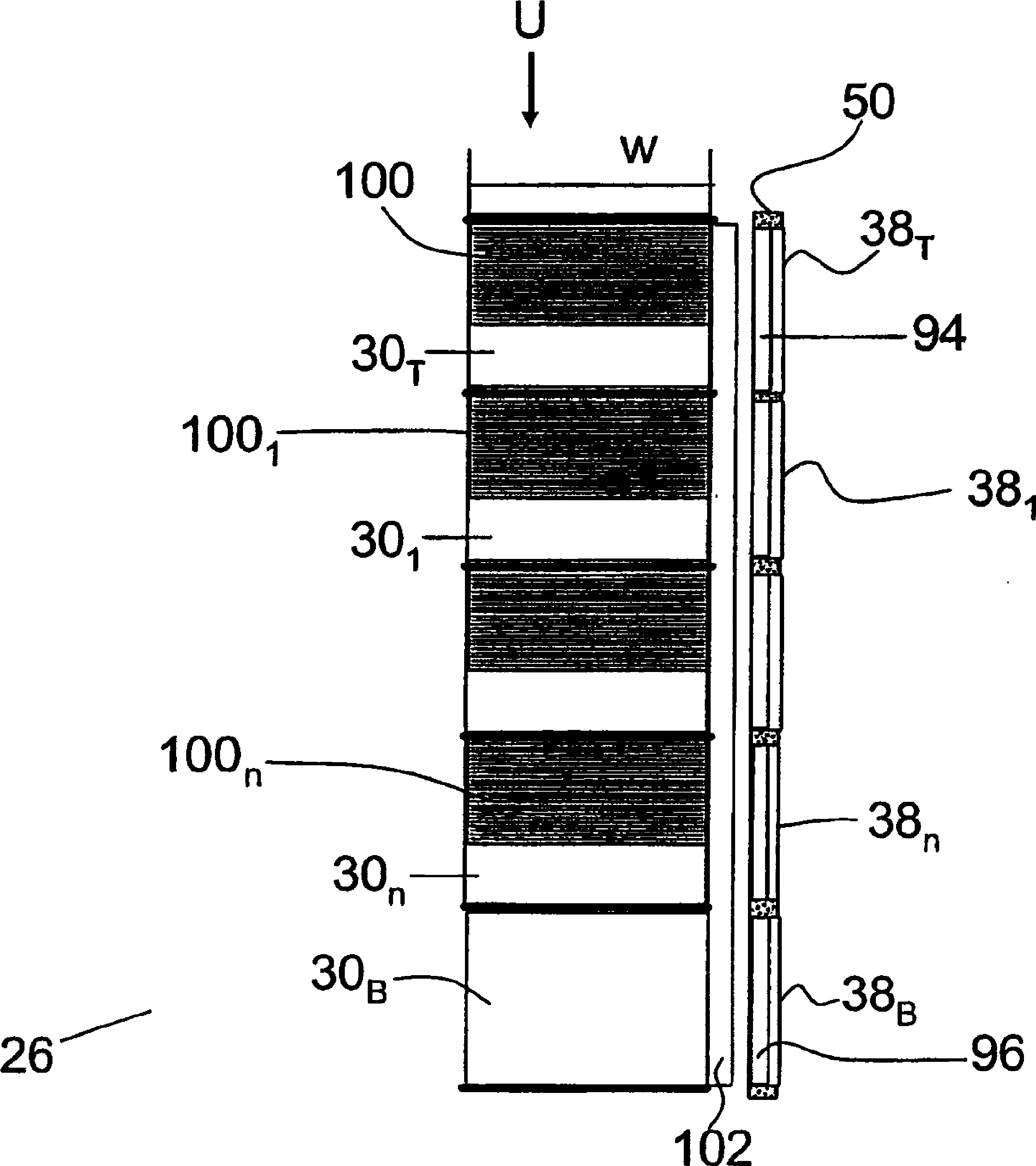
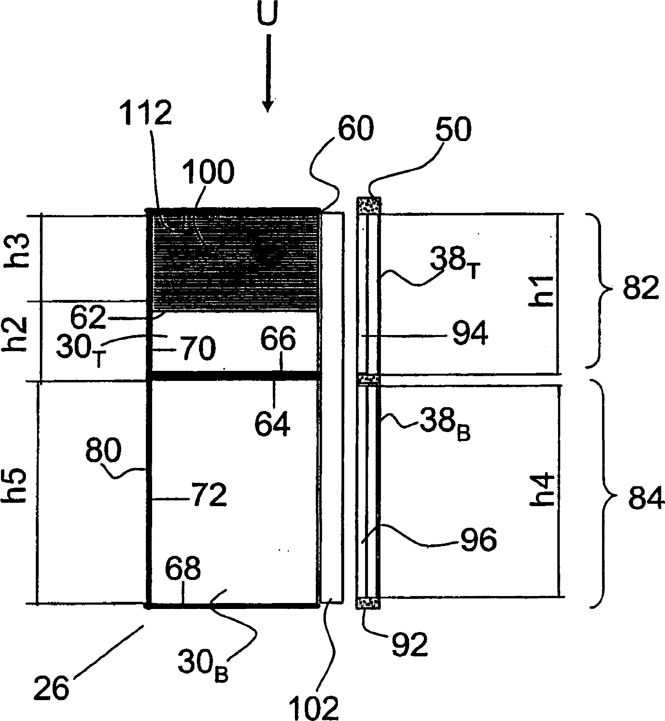
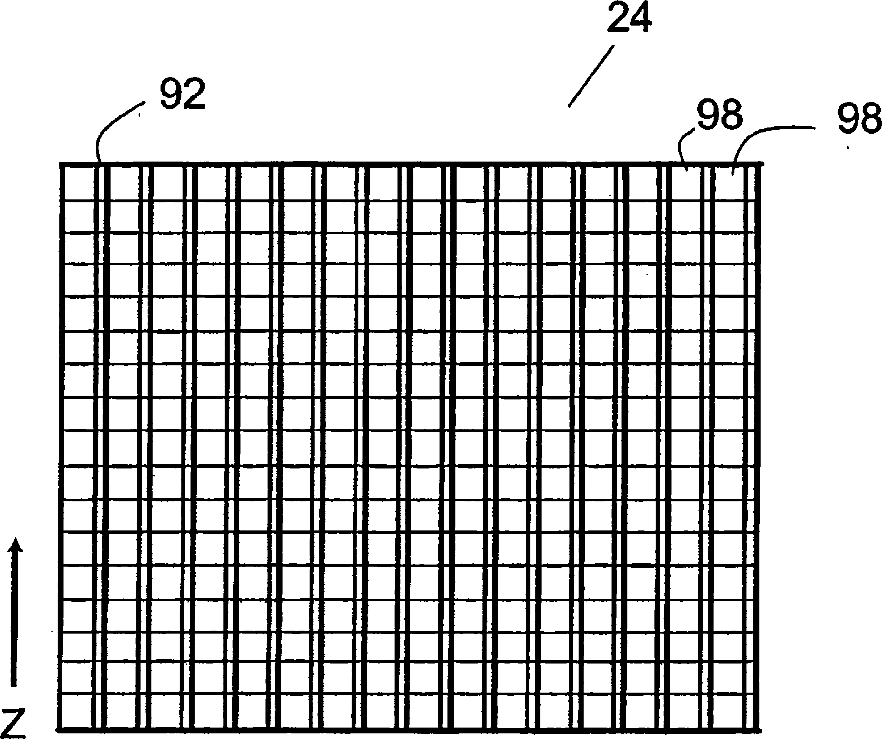
A radiation detector (24) includes a two-dimensional array of upper scintillators (30T) which is disposed facing an x-ray source to convert lower energy radiation events into visible light and transmit higher energy radiation. A two-dimensional array of lower scintillators (30B) is disposed adjacent the upper scintillators (30T) distally from the x-ray source (14) to convert the transmitted higher energy radiation into visible light. Upper and lower photodetectors (38T, 38B) are optically coupled to the respective upper and lower scintillators (30T,30B) at an inner side (60) of the scintillators (30T,30B). An optical element (100) is optically coupled with the upper scintillators (30T) to collect and channel the light from the upper scintillators (30T) into corresponding upper photodetectors (38T).

Description

technical field [0001] The invention relates to an application of an imaging system. The subject-matter of the invention relates to a particular application of a spectral computed tomography (CT) scanner, as will be described in detail hereinafter. However, the invention also relates to its use in combination with DF and RF imaging, X-ray fluoroscopy, radiography and other imaging systems for medical and non-medical examinations. Background technique [0002] Computed tomography (CT) imaging typically employs an x-ray source that produces a fan, wedge, or cone beam of x-rays that traverse the examination region. Objects arranged in the examination area interact with the traversing x-rays and absorb a part of them. A two-dimensional radiation detector comprising an array of detector elements is disposed opposite the x-ray source. The radiation detector includes a scintillator layer that measures the intensity of transmitted x-rays and an underlying photodetection layer. I...

Claims


Application Information

Patent Timeline
Patent Type & Authority Applications(China)
IPC IPC(8): G01T1/20G01T1/202G01T1/29
CPCG01T1/2985G01T1/202G01T1/2018Y10T29/49002G01T1/20183G01T1/20187G01T1/20185G01T1/20181G01T1/20182
Inventor S.莱文O.沙皮罗A.阿尔特曼N.韦纳
Owner KONINKLIJKE PHILIPS ELECTRONICS NV
Why Eureka
Try Eureka