Device and method for mounting CPLD (complex programmable logic device) chip

A chip and counting module technology, applied in the field of devices for loading CPLD chips, can solve problems such as conflicts, and achieve the effect of reliable loading

Active Publication Date: 2014-04-30
NEW H3C TECH CO LTD
View PDF4 Cites 6 Cited by
  • Summary
  • Abstract
  • Description
  • Claims
  • Application Information

AI Technical Summary

Problems solved by technology

However, if the GPIO output of the CPU is in a low-level state when the CPU is powered on and reset, and the enable terminal OE is in a valid state, then it will also cause a conflict between J1 and GPIO

Method used


Image

  • Device and method for mounting CPLD (complex programmable logic device) chip
  • Device and method for mounting CPLD (complex programmable logic device) chip
  • Device and method for mounting CPLD (complex programmable logic device) chip

Examples


Embodiment Construction

[0035] In order to make those skilled in the art more clear and understandable, the technical solution of the present invention will be clearly and completely described below in conjunction with exemplary embodiments of the present invention.

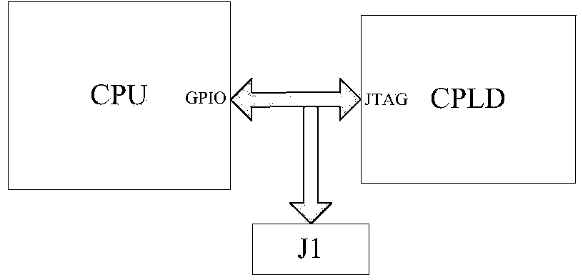
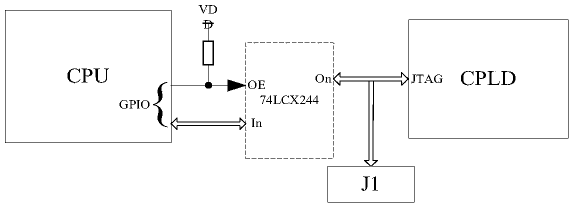
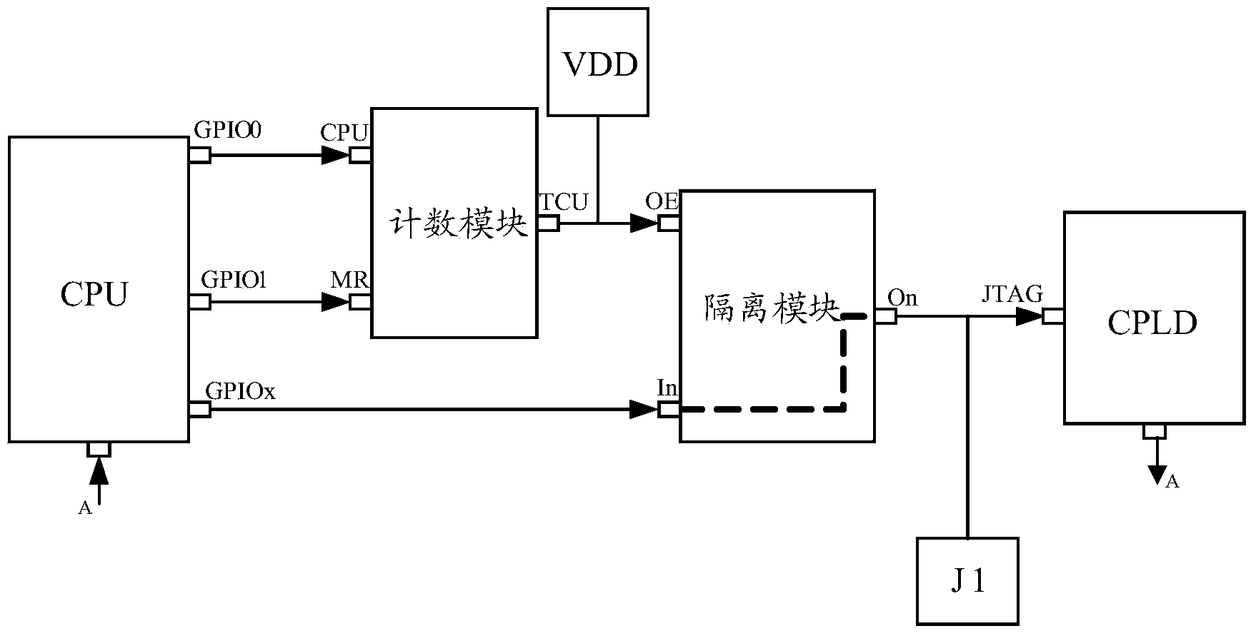
[0036] Such as image 3 As shown in FIG. 1 , it is a schematic diagram of hardware connection for loading a CPLD chip provided by an exemplary embodiment of the present invention. In this figure, the special JTAG interface for loading the CPLD chip software is respectively connected to the isolation pin ON of the isolation module and the loading socket J1; the isolation module is connected to the GPIOx pin of the CPU through the input pin In, and connected to the counting pin through the control pin OE The overflow pin TCU of the module receives the count overflow signal from the counting module. When the count overflow signal is received, the control isolation pin ON is in a low-impedance state, so that the GPIOx pin of the CPU can sim...


PUM


Abstract

The invention discloses a device and a method for mounting a CPLD (complex programmable logic device) chips. The device and the method have the advantages that only a low-cost counting module is additionally arranged between a CPU (central processing unit) and an isolation module, so that time sequences of special JTAG (joint test action group) interfaces can be assuredly simulated by GPIO (general purpose input/output) pins of the CPU no mater whether GPIO ports are in high-level states or low-level states or high-impedance states when the CPU is powered on and reset, and the CPLD chip can be reliably mounted for upgrading/updating software.

Description

technical field [0001] The invention relates to the technical field of communication, in particular to a device and method for loading a CPLD chip. Background technique [0002] For existing communication equipment, functions such as watchdog, interrupt aggregation, IO control and indicator light driving are generally implemented through CPLD (Complex Programmable Logic Device, complex programmable logic device) chips. For manufacturers, the initial design of CPLD products will inevitably have defects. If all defective products are recalled, it will not only be costly, but also increase the time for users to stop using it. In order to reduce costs and improve user satisfaction, existing solutions generally repair CPLD product defects by loading and upgrading software. That is, when the initially designed CPLD chip is defective, it is solved by issuing new upgrade software. [0003] Currently, the most commonly used loading method is to load the CPLD chip through the JTAG ...

Claims


Application Information

Patent Timeline
Patent Type & Authority Applications(China)
IPC IPC(8): G06F9/445
Inventor 李亮忠
Owner NEW H3C TECH CO LTD
Why Eureka
Try Eureka