Triangular concentric circular ring distribution array electromagnetic shielding optical window with internally-tangent sub circular rings

A concentric ring, electromagnetic shielding technology, applied in the direction of magnetic/electric field shielding, electrical components, etc., can solve the problems of low imaging quality and concentrated stray light distribution, and achieve the effect of improving electromagnetic shielding effect and uniformity.

Active Publication Date: 2014-04-30
HARBIN INST OF TECH
View PDF10 Cites 2 Cited by
  • Summary
  • Abstract
  • Description
  • Claims
  • Application Information

AI Technical Summary

Problems solved by technology

[0019] The purpose of the present invention is to overcome the shortcomings of the above-mentioned existing optical window electromagnetic shielding technical solutions, especially for the existing single-layer grid metal grid, single-layer ring grid, double-layer grid and ring grid. In order to solve the problem of relatively concentrated stray light distribution caused by sub-diffraction, a concentric ring triangular distribution array electromagnetic shielding light window with inscribed sub-rings was developed to achieve the purpose of depth homogenization of high-order diffraction and extremely low impact on imaging quality

Method used


Image

  • Triangular concentric circular ring distribution array electromagnetic shielding optical window with internally-tangent sub circular rings
  • Triangular concentric circular ring distribution array electromagnetic shielding optical window with internally-tangent sub circular rings
  • Triangular concentric circular ring distribution array electromagnetic shielding optical window with internally-tangent sub circular rings

Examples


Embodiment Construction

[0061] The present invention is further described below with reference to accompanying drawing and preferred embodiment:

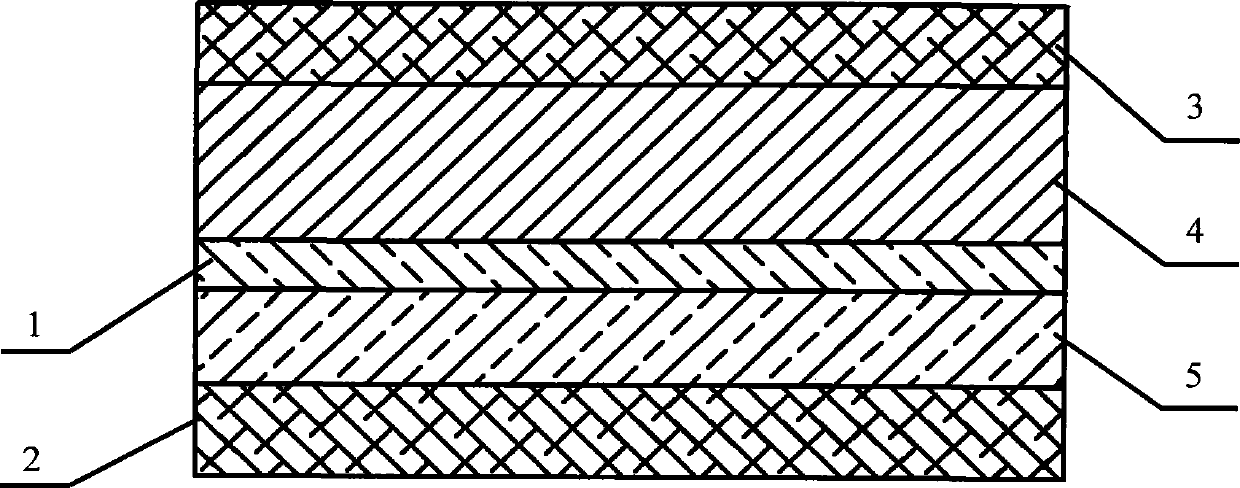
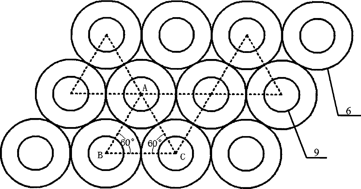
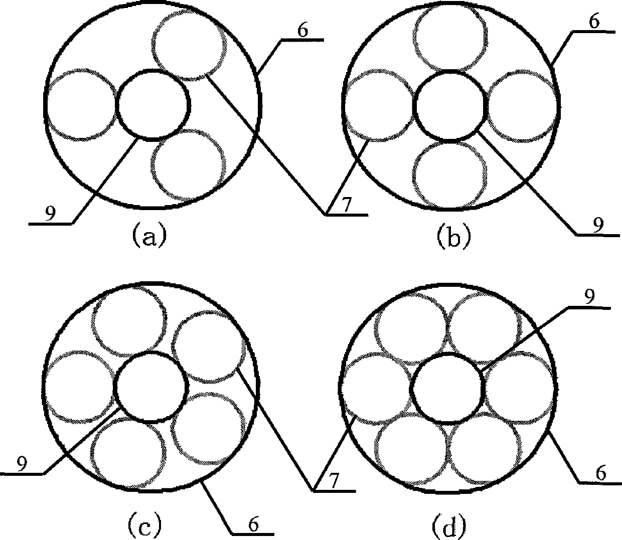
[0062] The concentric circular triangular distribution array electromagnetic shielding light window with inscribed sub-rings, the metal grid 5 in the electromagnetic shielding light window is composed of a group of concentric metal ring pairs arranged closely in an equilateral triangle and loaded on the transparent light window On the surface of the substrate, the diameters of the outer rings 6 of each pair of concentric rings are equal, and the outer rings 6 of adjacent pairs of concentric rings are circumscribed and connected; each pair of concentric rings has an outer circle with the pair of concentric rings. The ring 6 is inscribed and connected, and the metal sub-rings 7, the concentric rings and the inscribed sub-rings 7 together form the basic unit of the two-dimensional grid structure; the concentric metal rings and their inscribed The diameter of ...


PUM


Abstract

The invention discloses a triangular concentric circular ring distribution array electromagnetic shielding optical window with internally-tangent sub circular rings, and belongs to the technical field of electromagnetic shielding. One set of concentric metal circular rings are arranged according to an equilateral triangle, tightly connected to form a metallic mesh and loaded on the surface of a transparent substrate of the optical window. External circular rings of each concentric circular ring pair are equal in diameter, and the adjacent external circular rings are communicated in an externally-tangent mode. Each concentric circular ring pair is internally provided with one sub circular ring, wherein the sub circular ring is communicated with the external circular ring of the corresponding concentric circular ring pair in an internally-tangent mode. A basic unit of the two-dimensional metallic mesh is jointly composed of the concentric circular ring pairs and the sub circular rings internally tangent with the concentric circular ring pairs. The diameter of each circular ring is of the millimeter magnitude and the submillimeter magnitude. The width of each line is of the millimeter magnitude and the submillimeter magnitude. It is ensured that all the circular rings are mutually conductive at the positions where the circular rings are communicated in a tangent mode through line overlapping or the arrangement of metal capable of ensuring reliable electric linkage between tangency points of the metal rings. According to the structure of the metallic mesh, inhomogeneity of high-level diffraction light distribution of the mesh can be remarkably reduced, so that distribution of stray light caused by diffraction is more even, and the influence on imaging is smaller.

Description

technical field [0001] The invention belongs to the field of electromagnetic shielding of optical transparent parts, in particular to an electromagnetic shielding light window with a triangular distribution array of concentric rings with inscribed sub-rings. Background technique [0002] With the widening and increasing intensity of the electromagnetic wave application spectrum, the requirements for electromagnetic shielding optical windows used in aerospace equipment, advanced optical instruments, communication equipment, medical diagnostic instruments and security facilities are getting higher and higher, mainly requiring optical windows While having a super strong broadband electromagnetic shielding ability, it also has a very high light transmittance, and the less impact on optical imaging, observation, and detection, the better. For example, the optical windows of aircraft in the field of aerospace equipment must achieve high-quality isolation of electromagnetic signals...

Claims


Application Information

Patent Timeline
Patent Type & Authority Applications(China)
IPC IPC(8): H05K9/00
Inventor 陆振刚谭久彬
Owner HARBIN INST OF TECH
Why Eureka
Try Eureka