Plate-integrated gasket

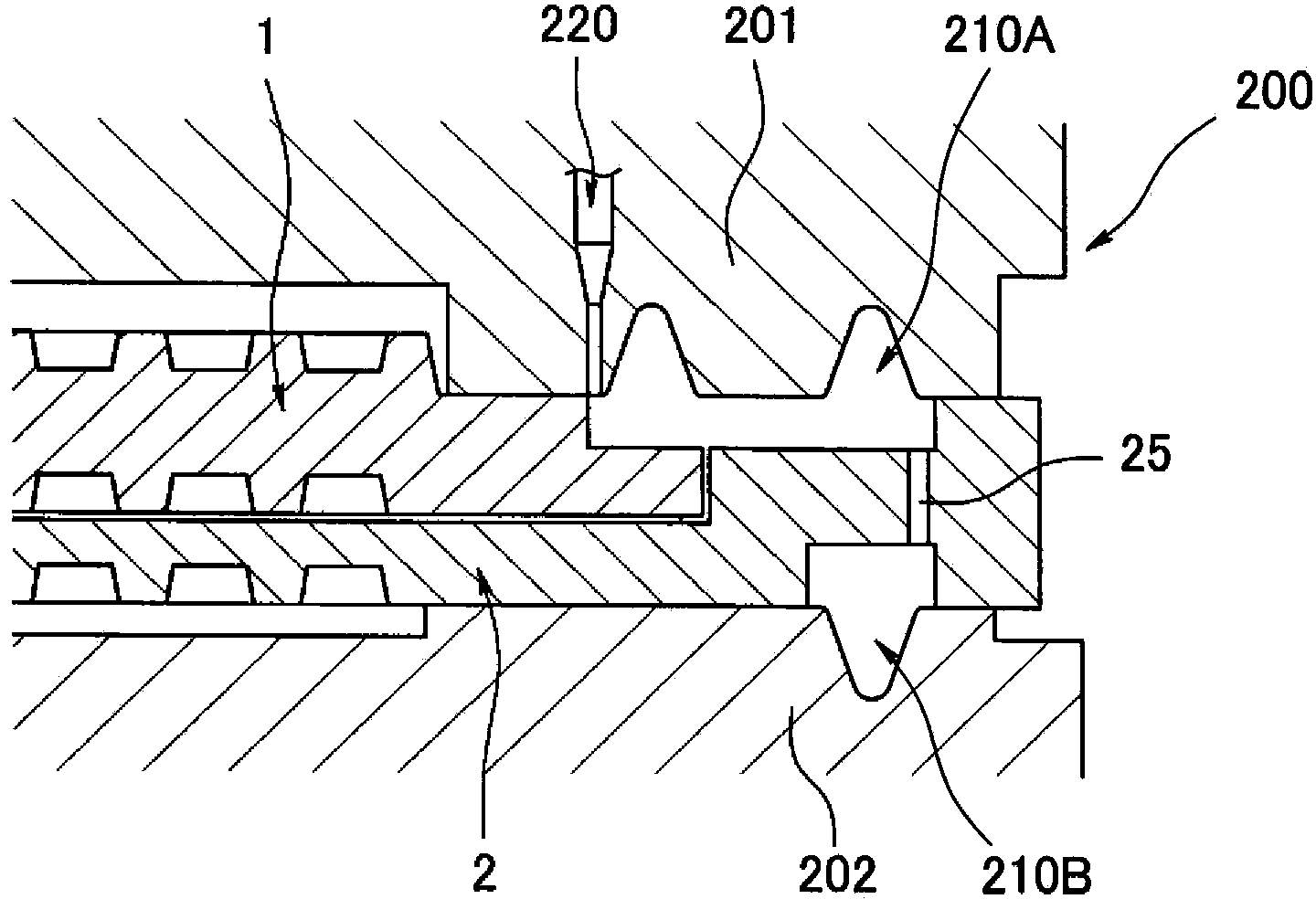
An integrated, plate technology, applied in the direction of fuel cells, electrochemical generators, electrical components, etc., can solve the problems of consistent compressibility characteristics, increase in fuel cell size, complex structure of the mold 200, etc., to improve productivity and prevent deviation. Effect

Active Publication Date: 2014-04-30
NOK CORP
View PDF7 Cites 21 Cited by
  • Summary
  • Abstract
  • Description
  • Claims
  • Application Information

AI Technical Summary

Problems solved by technology

[0008] However, if Figure 25 As shown in the example shown in , since there is a height difference in the stacking direction between the first separator 101 and the second separator 102, the seal member 103 on the separator 101 side and the seal member 105 on the second separator 102 side In this case, it is difficult to make the seal members 103, 105 in the assembled state equal in characteristics such as compressibility
[0009] And, in Figure 24 as well as Figure 25 In the conventional example, because the following structure is formed, that is, not only the outer peripheral dimension of the second separator 102 is larger than the outer peripheral dimension of the first separator 101, but also the sealing members 103, 105 are restricted with respect to the inner and outer peripheral directions. The sealing and fixing grooves 101c and 102d are respectively provided on the first partition 101 and the second partition 102, so the width w of the region where the sealing members 103 and 105 are provided and Figure 23 becomes larger compared to the example, as a result, the size of the fuel cell as a whole increases
[0010] further, such as Figure 26 As shown, since the mold 200 used in the molding needs to be used to fill the molding rubber material into the cavity 203 required for forming the sealing member 103 on the first separator 101 side, and the sealing member on the second separator 102 side, respectively. 104, 105 require multiple injection ports 203a, 204a of the cavity 204, so it is pointed out that there is a problem that the structure of the mold 200 becomes complicated

Method used


Image

  • Plate-integrated gasket
  • Plate-integrated gasket
  • Plate-integrated gasket

Examples


Embodiment Construction

[0078] Hereinafter, preferred embodiments in which the plate-integrated gasket according to the present invention is applied to a fuel cell gasket will be described in detail with reference to the drawings.

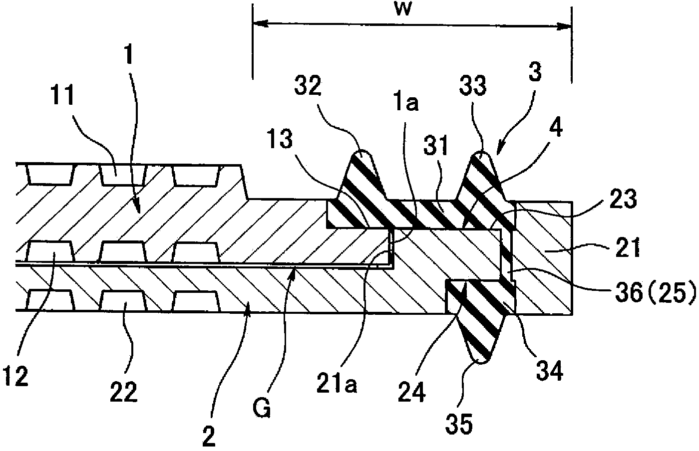
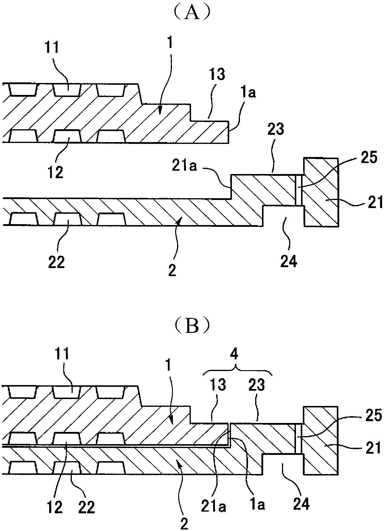
[0079] first, figure 1 It is a view showing a double-sided lip gasket for a fuel cell as a first embodiment. In this sealed structure, reference numerals 1 and 2 are respectively plate-shaped separators made of a conductive material such as carbon, and correspond to the plate material described in claim 1 . The separators 1 and 2 are stacked on top of each other, and at the same time, the outer peripheral surface 1a of the upper first separator 1 in the figure fits into the stepped surface formed along the outer peripheral portion 21 of the lower second separator 2 toward the inner peripheral side. 21a.

[0080] The first flow path groove 11 is formed on the upper surface of the first separator 1 , and the second flow path groove 12 is formed on the opposite surface, t...


PUM


Abstract

The purpose of the present invention is to provide a plate-integrated gasket configured so that a seal member (3), which is provided to plates (1, 2) laminated on each other, can be mounted within a reduced width and so that the gasket can be manufactured with increased productivity. In order to achieve the purpose, the plate-integrated gasket is configured so that one plate (1) and the other plate (2) are laminated on each other, the outer peripheral surface (1a) of the one plate (1) is fitted or loosely fitted in a stepped surface (21a) formed in the other plate (2), the seal member (3) consisting of an elastic material having rubber-like elasticity is integrally formed on the one plate (1) and the other plate (2) so as to straddle both the plates (1, 2), and the gasket has an affixed section (31) filled into a seal affixation groove (4) formed between the one plate (1) and the other plate (2).

Description

[0001] technology area [0002] The present invention relates to a plate-integrated gasket in which a sealing member made of an elastic material having rubber-like elasticity is integrated in a structure in which a plurality of plates are stacked to seal a flow path between them, such as a fuel cell. on the plate. Background technique [0003] As a board-integrated gasket utilizing existing technology, Figure 23 An example of a fuel cell gasket in which a sealing member made of an elastic material having rubber-like elasticity is integrated with a fuel cell separator is shown. [0004] In this fuel cell gasket, reference numerals 101 and 102 respectively denote plate-shaped separators made of conductive materials such as carbon. Among them, in Figure 23 On the upper surface of the first separator 101 on the upper side, a channel groove 101a for supplying one of gaseous fuel (hydrogen gas) and oxidant gas (air) is formed, and at the same time, it is integrally bonded for sea...

Claims


Application Information

Patent Timeline
Patent Type & Authority Applications(China)
IPC IPC(8): F16J15/10H01M8/02
CPCH01M8/0284Y02E60/50F16J15/022F16J15/0825F16J15/104F16J15/123F16J2015/085F16J2015/0856H01M8/0247H01M8/0273H01M8/0276H01M8/0297Y02P70/50H01M8/0258H01M8/0267
Inventor 岛添稔大渡部茂
Owner NOK CORP
Why Eureka
Try Eureka