
Serrated shaft debris collector

A collector and sawtooth technology, applied in the direction of couplings, rigid shaft couplings, metal processing equipment, etc., can solve the problems of component complexity, falling off, time-consuming, etc.

Active Publication Date: 2014-05-07
GM GLOBAL TECH OPERATIONS LLC
View PDF6 Cites 8 Cited by
  • Summary
  • Abstract
  • Description
  • Claims
  • Application Information

AI Technical Summary

Problems solved by technology

The same is true for chips, which remain attached at first, but fall off in use
Ensuring all debris is removed through the sweeping process is often time consuming and, resulting in the complexity of many components including channels, vias, blind holes, etc., may not always yield the desired results

Method used


Image

  • Serrated shaft debris collector
  • Serrated shaft debris collector
  • Serrated shaft debris collector

Examples


Embodiment Construction

[0052] The following description is merely exemplary in nature and is not intended to limit the invention, application or use.

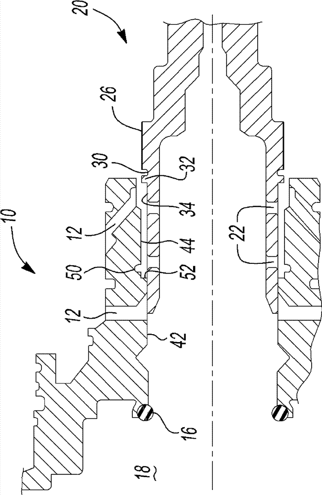
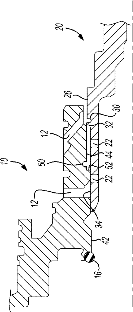
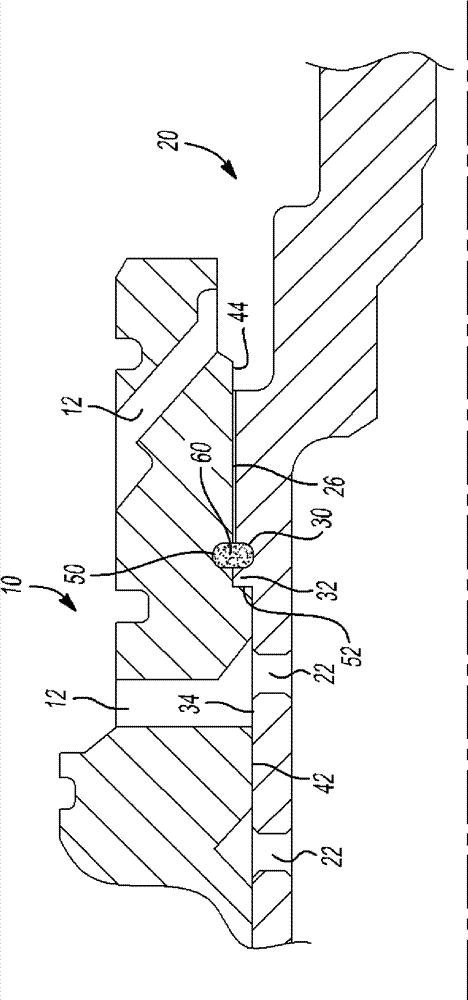
[0053] refer to figure 1 , 2 and 3 , show a housing, which may be, for example, a rotating component of an automatic transmission or other power transmission or transmission device, and is generally designated with reference number 10 . It will be appreciated that housing 10 is exemplary and illustrative only and that other components such as gears, pulleys, bearings, etc. may be used in its place. The housing 10 is circular, preferably made of a light and soft material such as aluminum, and includes a plurality of radially inclined channels 12 and external features such as splines or gear teeth (not shown) and can be accommodated in associated A cylindrical outer wall 14 within the component (also not shown). The housing 10 may also include an annular resilient seal 16 that engages and seals against a central region 18 of the housing 10 .

[005...


PUM


Abstract

The invention relates to a serrated shaft debris collector. A chip or debris trap or collector are provided which retains metal chips, fragments and other debris generated when a serrated or splined, press fit connection is assembled between a shaft and another component such as a housing, gear, pulley or bearing. The chip collector includes a circumferential channel or groove disposed about the shaft adjacent the ring of serrations or male splines and an adjacent circumferential flange. An optional second channel or groove resides in the other component. As the shaft and the component are assembled, chips, fragments or other debris generated by the interference fit and axial sliding assembly of the components are collected in the channel or groove and retained there as the shaft fully seats within the other component.

Description

technical field [0001] The present invention relates to a chip collector for a serrated shaft, and more particularly to a collector for chips and debris generated by press fitting a serrated or splined shaft into a complementary component. Background technique [0002] The statements in this section merely provide background information related to the present disclosure and may or may not constitute prior art. [0003] Many driveline components such as shafts, gears, pulleys, bearings, etc. are assembled from one component to another by press fitting. This may involve one of several methods: heating the outer part to expand it slightly while seating it on the inner part and allowing it to cool, or, giving a very small interference fit, simply squeezing a part into the on the other or in the other. Press fits will often include external serrations mounted in smooth bores, or complementary internal and external splines, both of which greatly increase the torque carrying capa...

Claims


Application Information

Patent Timeline
IPC IPC(8): B23P19/02
CPCF16D2001/103F16D1/10F16D1/072F16D1/06Y10T403/16
Inventor C.G.哈蒙D.G.埃迪F.D.路易斯
Owner GM GLOBAL TECH OPERATIONS LLC
Learn More