

Porous structure body and method of forming it
a technology of porous structure and forming method, which is applied in the direction of chemistry apparatus and processes, cores/yokes, transportation and packaging, etc., can solve the problems of deteriorating dimensional accuracy of finished products and the ready-to-distortion of intermediate products, and achieves high anti-vibration and thermal insulation properties, high strength, and high strength.
- Summary
- Abstract
- Description
- Claims
- Application Information
AI Technical Summary
Benefits of technology
Problems solved by technology
Method used
Image

Examples
example 2
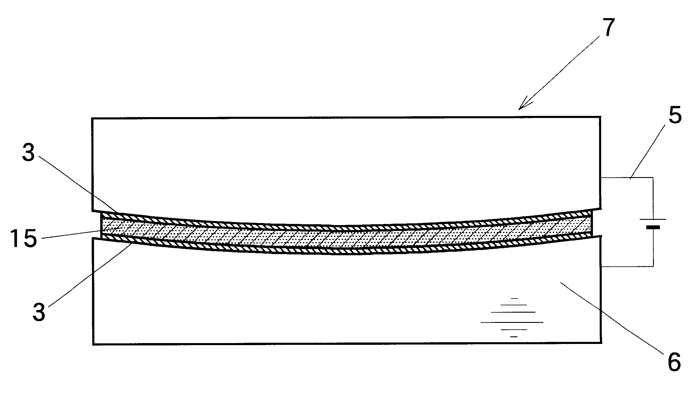
In the primary molding apparatus, after a separation sheet was placed on the bottom surface of the molding frame, 6 kg of shaved particles or abatements of aluminum-silicone alloy containing 20% silicone was charged and leveled so as to be about 50 mm in thickness. Further, a separation sheet was flatly placed on the surface of the shaved particles.
Next, a pressing die was lowered, and simultaneously, the electric power was turned on. Now, the metal chips were pressed at an electric voltage of 20 volts. The pressurization was continued at a pressure of 10 kg / cm.sup.2. After pressing for about 3 minutes, the current strength reached the equilibrium at 4500 to 5000 amperes. Then, the pressing die was lifted, and the intermediate product 1 was removed.
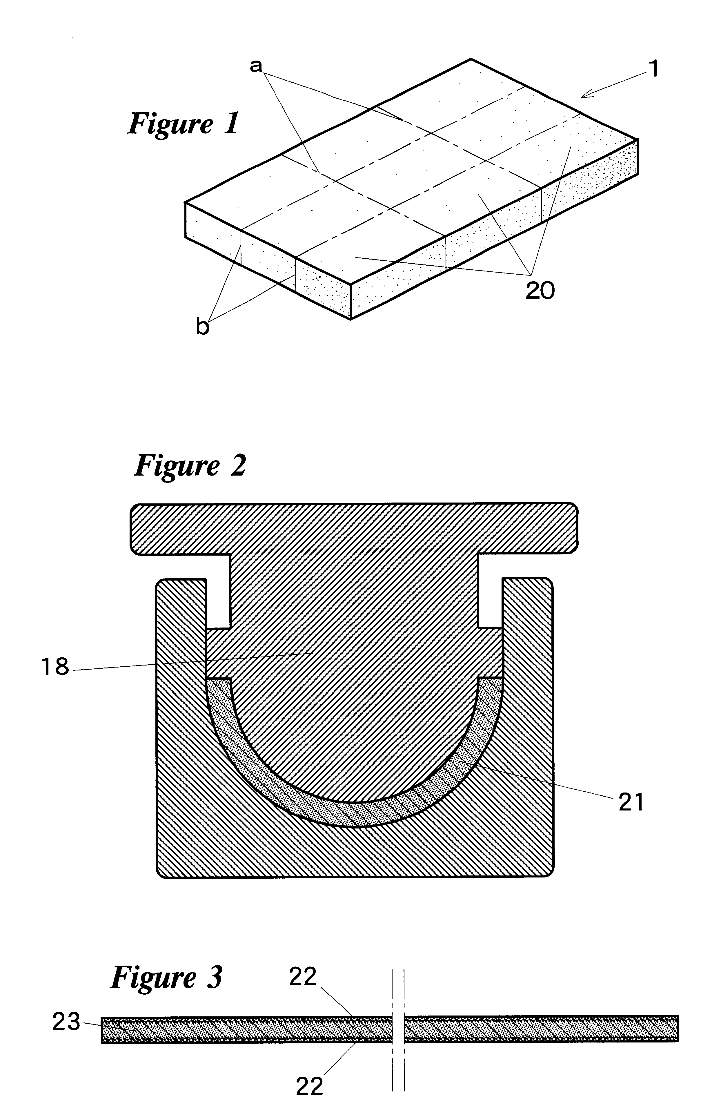
The obtained intermediate product 1 in its fevered state, having a flat plate shape, was removed from the primary molding apparatus. The intermediate product 1 was longitudinally cut to equal lengths along the straight line b shown in FIG...
example 3
12 kg of the same the shaved particles of cast iron containing about 3.5% carbon as used in Example 1 was mixed with 5 kg of the shaved particles of common steel containing 0.5% carbon (manufactured by Sin-Nippon Steel Corporation). Thus, metal chips comprising the shaved particles of the cast iron and those of the carbon steel were obtained. In the primary molding apparatus, after a separation sheet was placed on the bottom surface of the molding frame, 17 kg of the particles comprising the cast iron shave particles and the common steel shaved particles were charged and leveled so as to be about 50 mm in thickness. Further, a separation sheet was flatly placed on the surface of the particles.
Next, the pressing die was lowered, and simultaneously, the electric power was turned on. The particles were pressed at a voltage of 20 volts by lowering the pressing die. Then, the carburizing phenomena occurred, in which the carbon contained in the shaved particles of the cast iron were migra...
example 4
15 kg of the same shaved particles or abatements of the cast iron as used in Example 1 was mixed with 3 kg of glass particles with an average diameter of 1 mm to obtain metallic chips. A thin paperboard was placed on the bottom surface of the molding frame of the primary molding apparatus. Water was sprayed on the surface of the paperboard. Succeedingly, 12 kg of the above-described particles was uniformly charged on the paper board. Further, a thin paper board onto which water was sprayed was placed thereon.
Next, the pressing die was lowered, and simultaneously, the electric power was turned on. After pressing for 1 to 2 minutes, the temperature in the molding frame reached 850 to 1000.degree. C. When the temperature became 1000.degree. C., the current was stopped, and the intermediate product 1 was removed.
The obtained intermediate product 1 in its fevered state, having a flat plate shape, was removed from the primary mold. For example, the intermediate product 1 was cut longitudi...
PUM
| Property | Measurement | Unit |
|---|---|---|
| Fraction | aaaaa | aaaaa |
| Percent by mass | aaaaa | aaaaa |
| Temperature | aaaaa | aaaaa |
Abstract
Description
Claims
Application Information