

Wringer suitable for loose fiber or loose fiber cake dehydration
A loose fiber and water press technology, which is applied in the processing of textile materials, liquid/gas/vapor removal with squeeze rollers, textiles and papermaking, etc. The problem of high electrical energy consumption can reduce the difficulty of washing, reduce washing time, and reduce water consumption.
- Summary
- Abstract
- Description
- Claims
- Application Information
AI Technical Summary
Problems solved by technology
Method used
Image

Examples
Embodiment 1
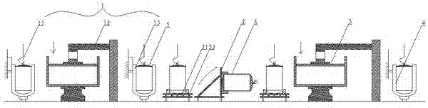
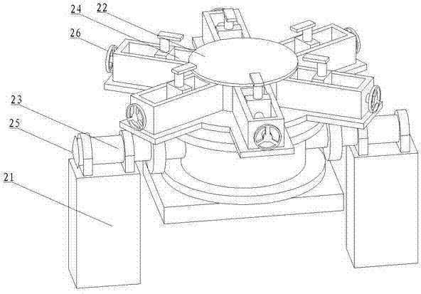
[0022] combine figure 1 , the present embodiment is a water extractor suitable for dehydration of bulk fiber or bulk fiber cake. The water extractor of the present invention is applied in the bulk fiber cold pad batch dyeing line. Cold pile machine 2, using the water press to dye bulk fibers, sequentially through the dipping device 1 (exhaust dyeing device one 11→drying device 12→exhaust dyeing device two 13), rotatable cold pile machine 2 and water squeezer 3, of which:
[0023] (1) Squeezing device: Squeezing device 1 includes a dipping device 11, a drying device 12 and a dipping device 2 13, and the loose fibers are sequentially passed through a dipping device 11, a squeezing device 12 and a dipping device 2 13 for two dipping and one squeezing , the bulk fiber or bulk fiber cake is first dip-dyeed in the dip-dyeing device-11, the first dip-dyeing serves the purpose of pretreatment, and the loose fiber or bulk fiber cake of the outer layer is moistened first; the loose fib...
Embodiment 2
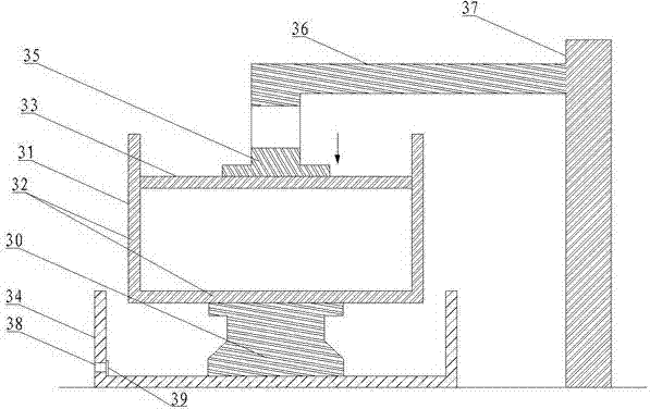
[0029] The setting and working principle of this embodiment are the same as that of Embodiment 1, the difference is that: under the cylindrical cylinder 31 of the water extractor 3, a liquid collection tank 34 is arranged around the base 30, and the liquid collection tank 34 is provided with a liquid discharge port 38. A strainer 39 is provided at the discharge port 38, and the liquid collecting tank 34 is located under the cylindrical cylinder body 31. The liquid containing dyes and auxiliaries in the loose fibers or fabrics flows out through the leak hole 32 and then gathers in the collecting tank 34 , and then through the liquid discharge port 38, the collected liquid is emptied, and the filter screen 39 can prevent the fibers from blocking the liquid discharge port 38, and avoid bringing it into the subsequent washing, and concentrate the liquid to reduce the subsequent washing. While the work is difficult, the collected liquid can be recycled and reused, which can realize ...
Embodiment 3
[0031] The setting and working principle of this embodiment are the same as that of Embodiment 1, the difference is that: under the cylindrical cylinder 31, a liquid collection tank 34 is arranged around the base 30, and the liquid collection groove 34 is provided with a liquid discharge port 38, and the liquid discharge A filter screen 39 is provided at the mouth 38, and the liquid collecting tank 34 is located under the cylindrical cylinder body 31. After the liquid containing dyes and auxiliary agents in the loose fibers or fabrics flows out through the leak hole 32, it is concentrated in the liquid collecting tank 34, and then passed through The drain port 38 is used to empty the collected liquid, and the filter screen 39 can prevent the fiber from blocking the drain port 38 and avoid bringing it into the subsequent washing. The liquid is treated centrally to reduce the difficulty of subsequent washing work. , the collected liquid can be recycled and reused, which can reali...
PUM
| Property | Measurement | Unit |
|---|---|---|
| Aperture | aaaaa | aaaaa |
| Aperture | aaaaa | aaaaa |
| F | aaaaa | aaaaa |
Abstract
Description
Claims
Application Information