
Corrugated pipe structure based self-compensating electric ball valve

An electric ball valve and bellows technology, applied in valve devices, engine components, cocks including cut-off devices, etc., can solve the problems of low reliability of action performance and poor sealing performance of electric ball valves, and achieve low mechanical wear and good sealing performance. , the effect of avoiding wear

Inactive Publication Date: 2014-05-07
NUCLEAR POWER INSTITUTE OF CHINA
View PDF5 Cites 0 Cited by
  • Summary
  • Abstract
  • Description
  • Claims
  • Application Information

AI Technical Summary

Problems solved by technology

[0004] The purpose of the present invention is to provide a shielded electric ball valve with good sealing performance and high reliability, which can solve the problem of poor sealing performance and low reliability of action performance of the electric ball valve in the pipeline system under high temperature and submerged environment conditions. question

Method used


Image

  • Corrugated pipe structure based self-compensating electric ball valve

Examples


Embodiment Construction

[0018] The present invention will be described in detail below in conjunction with the accompanying drawings and specific embodiments.

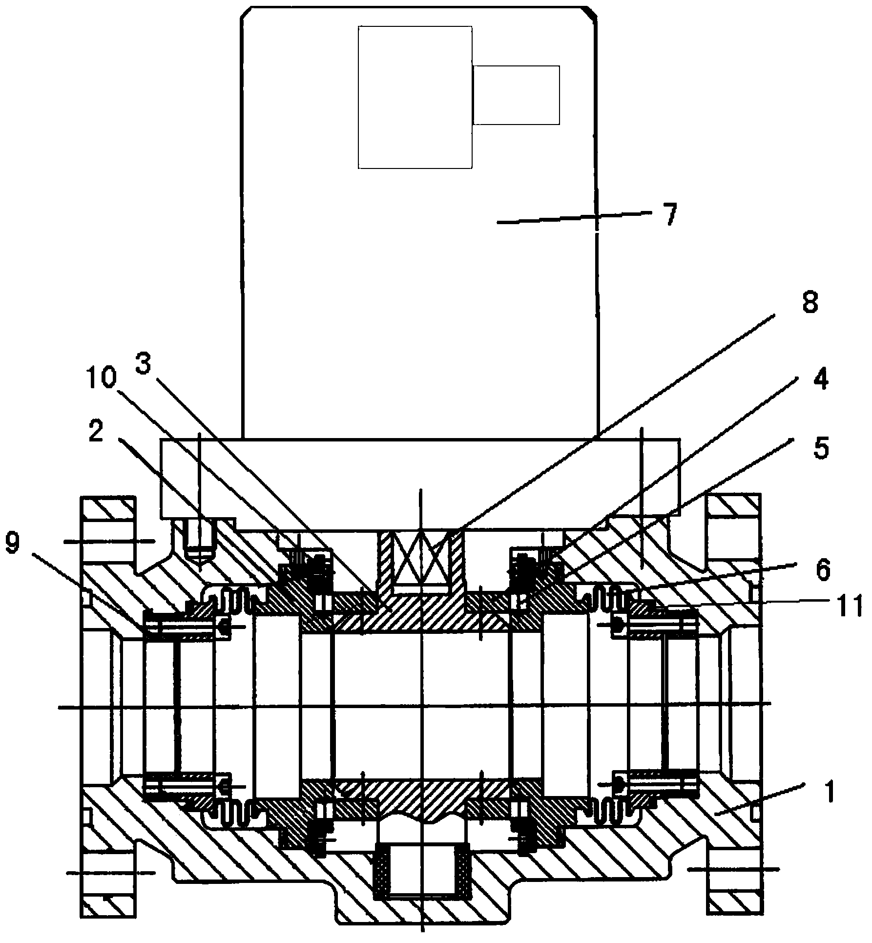
[0019] Such as figure 1 As shown, the lower end of the motor 7 is processed with a flange, and the flange at the lower end of the motor 7 is connected to the valve body 1 by bolts, thereby fixing the motor 7 and the valve body 1 . The motor 7 is energized to drive the valve stem 8 below it to rotate, and the lower end of the valve stem 8 is processed into a square column structure.

[0020] A sphere 3 is installed in the valve body 1, and the upper end of the sphere 3 is processed with a square hole. The square column at the lower end of the above-mentioned valve stem 8 is connected with the square hole on the sphere 3, so that the valve stem 8 rotates to drive the sphere 3 to rotate together.

[0021] The cam 4 is fixedly installed on the ball 3 by screws, the rolling body 5 is installed outside the cam 4, the valve seat 2 fixedly installed...


PUM


Abstract

The invention relates to a technology of valves in fluid pipes and particularly discloses a corrugated pipe structure based self-compensating electric ball valve. The electric ball valve comprises a valve body, a valve seat fixed in the valve body, a ball arranged in the valve seat, a motor connected with the upper end of the ball and a corrugated pipe arranged on the outside of the valve seat. A locator is arranged on the outside of the corrugated pipe and fixedly connected with the valve seat. A cam is fixed on the ball, and a rolling element is arranged on the outside of the cam and arranged between the cam and the valve seat. By means of the corrugated pipe structure, dynamic seal is performed, and the seal performance is good; meanwhile, abrasions to a graphite seal ring are prevented, and the service life of the graphite seal ring is increased; the corrugated pipe is located through the locator, so that the compensation performance is improved; by the aid of the cam and rolling element structure, mechanical abrasions to the cam are minimized, friction-free moving of the valve seat and the valve body during ball valve opening and closing is guaranteed, and the service life is increased.

Description

technical field [0001] The invention belongs to the valve technology in the fluid pipeline, in particular to an electric ball valve. Background technique [0002] The current electric ball valves usually meet the functional requirements under the normal operating environment of the pipeline system. However, when the valve equipment is in a high-temperature environment, because the whole structure is submerged by high-temperature media, higher requirements are put forward for the sealing performance of the electric ball valve. On the other hand, the shielded electric ball valve is in the closed state when the system is in normal operation. It must ensure reliable operation in high temperature and submerged environments, and provide a flow channel for the medium to achieve the expected function of the system. Therefore, the operation reliability of the valve requires higher. At present, in view of the problems of the existing electric ball valves such as low temperature resis...

Claims


Application Information

Patent Timeline
Patent Type & Authority Applications(China)
IPC IPC(8): F16K5/06F16K5/20F16K5/08
CPCF16K5/06F16K5/08F16K5/20
Inventor 谭术洋关莉
Owner NUCLEAR POWER INSTITUTE OF CHINA
Learn More