Rotating connector

A technology of rotary joints and shells, which is applied in the direction of pipes/pipe joints/fittings, adjustable connections, passing components, etc., can solve the problems of joints that cannot be completed, gas leakage, easy leakage, etc., to improve stability and flexibility, The effect of increasing the service life and increasing the compensation amount

Inactive Publication Date: 2014-05-07
刘明
View PDF0 Cites 6 Cited by
  • Summary
  • Abstract
  • Description
  • Claims
  • Application Information

AI Technical Summary

Problems solved by technology

[0002] In the metallurgical industry, rotary rotary joints are often used, but problems such as short service life, liquid delivery, and gas leakage are often encountered, and the rotary O-ring device is basically used to solve them.
At present, it is often seen that the use of O-ring seals has problems such as easy wear, short life, and easy leakage.
For example: when the O-ring is worn, there will be leakage, etc., which will cause the joint to fail to complete the corresponding work

Method used


Image

  • Rotating connector

Examples


Embodiment Construction

[0009] The present invention will be further described below in conjunction with the accompanying drawings.

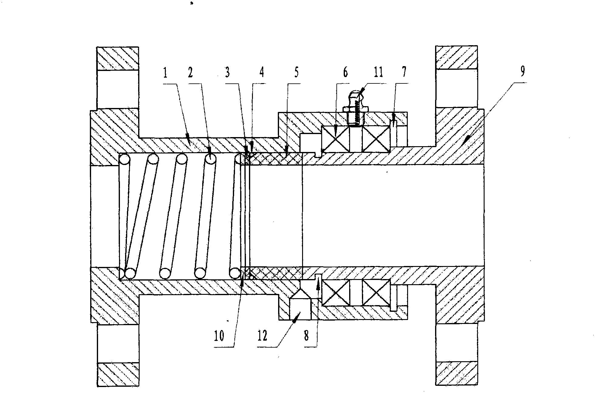
[0010] Such as figure 1 As shown, a rotary joint of the present invention includes: a housing 1, a spring 2, a rubber pad 3, an O-ring 4, a sealing ring 5, a bearing 6, a retaining ring 7 for a hole, a retaining ring 8 for a shaft, and a hollow shaft 9 1. The spring pad 10 is characterized in that: the spring 2 and the spring pad 10, the rubber pad 3, the O-ring 4, and the sealing ring 5 are arranged in the housing 1, the shaft clamp 8 is arranged in the groove of the hollow shaft 9, and the bearing 6 is arranged Between the inner hole of the housing 1 and the outer diameter of the hollow shaft 9, the grease nipple II fills the bearing 6 with lubricating oil, and the observation hole 12 is used to observe whether there is leakage. All components are connected as a whole by the retaining ring 7 for the hole.

[0011] Further, the sealing ring 5 is a graphite sealing r...


PUM


Abstract

The invention discloses a rotating connector. The rotating connector comprises a shell (1) and is characterized in that a spring (2), a spring cushion (10), a rubber cushion (3), an O-shaped ring (4) and a seal ring (5) are arranged in the shell (1), a shaft clamp (8) is arranged in a groove of a hollow shaft (9), a bearing (6) is arranged between an inner hole of the shell (1) and the external diameter part of the hollow shaft (9), lubricant oil is injected into the bearing (6) through an oil nozzle II, and an observation hole (12) is used for a worker to observe whether leakage exists or not. A hole check ring (7) is used for performing limiting to connect all components into a whole. The rotating connector has the advantages of being simple in structure, stable in supporting and large in bearing pressure, the resisted pressure is 2.0 MPa, the revolving speed is 0-500 r/min, the rotating connector is suitable for the operation of a pipeline, and media are cooling water, saturated steam, conduction oil, air and the like.

Description

technical field [0001] The invention relates to a rotary joint. Background technique [0002] In the metallurgical industry, rotary rotary joints are often used, but problems such as short service life, liquid and gas leakage are often encountered, and rotary O-ring devices are basically used to solve them. What is often seen at present is that the use of O-ring seals has problems such as easy wear, short life, and easy leakage. For example: when the O-ring is worn, there will be leakage, etc., which will cause the joint to fail to complete the corresponding work. Contents of the invention [0003] The present invention aims at the deficiencies of the above-mentioned prior art, and provides a rotary joint with simple structure, stable support and high pressure bearing. [0004] The technical solution of the present invention is: a rotary joint, including: housing 1, spring 2, rubber pad 3, O-ring 4, sealing ring 5, bearing 6, retaining ring 7 for hole, retaining ring 8 f...

Claims


Application Information

Patent Timeline
Patent Type & Authority Applications(China)
IPC IPC(8): F16L27/08
CPCF16L27/0808
Inventor 刘明
Owner 刘明
Why Eureka
Try Eureka